This thread has been locked.

If you have a related question, please click the "Ask a related question" button in the top right corner. The newly created question will be automatically linked to this question.

DRV421: Very high offset drift compared to typical value in datasheet

Part Number: DRV421

Hello E2E Experts,

Good day.

We are in the late stage of the development of a Residual Current Monitoring device (IEC62752 compliant) using the DRV421 IC. Recently, we performed high-low temperature tests on the device and discovered that the offset drift over temperature is quite high. It seems like the offset drift comes from the DRV421 having drift largely exceeding what was stated in the datasheet. This was found by measuring the voltage across RSHUNT over -30C ~ 60C, which is the shunt resistor in series with the compensation coil. Following is test results:

Test conditions: Zero primary currents, compensation coil 100 turns, RSHUNT = 100 ohms, nanocrystalline core (shape and dimensions in attachment core.pdf)

Test performed in the temperature chamber

Temperature C RSHUNT(mV)
-30 6.5
-25 6.2
-20 6.05
-15 5.99
-10 7.5
-5 5.44
0 4.9
5 4.6
10 4.11
15 3.8
20 2.9
25 2.2
30 1.7
35 1.2
40 0.5
45 -0.2
50 -0.8
55 -0.8
60 -1.02

As can be seen, the initial offset in mV (at 25 deg C) is around 2.2, which should correspond to the max. 8µT, typ.~1µT initial offset in magnetic flux density. But at 5 deg C, with only 20 deg C difference in temperature from 25 deg C, the change in offset is already 4.6mV -2.2mV = 2.4 mV, exceeding the initial offset. On the datasheet, typ. 5nT/°C is stated as offset drift. According to this information, a change in offset due to 20 deg C change in temperature should be around 10% of the initial offset in a typical case. (typ. 1µT initial offset / (5nT/°C  * 20°C ) = 0.1)

 Relevant schematic:

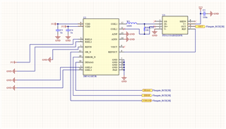
Could you advise on what could be the cause to this high offset drift, and what could be done to mitigate it? Thank you very much in advance!

Regards,

CSC

  • Hello CSC,

    I have a few questions.  I don't think you could get the value required for RCD with the DRV421.  The numbers you are showing are the best I have seen so maybe you can do it.  Please also share the attachement as this may give me some more insight and answer some questions below.

    • With 100 windings how are you able to get the loop stable.  The requirement is 100mH. 
    • What is your magnetic gain of the core.  Even with a small air gap the distance internally to the sensor will limit your gain this limit places you at about 800µT/A.  I normally see and average of 500µT/A.
      • Offset = 8µT, Core Gain 500µT/A -> Offset error = 8µT/(500µT/A)= 16mA.  This value is then goes across your 100Ω  Rshunt.
      • Typical Drift: 5nT/°C * 90° = 450nT  = 0.450µT/(500µT/A)= 0.9mA -> 0.9mA * 100Ω = 9mV 
      • Figure 5 max: 22nT/°C * 90° = 1.98nT  = 1.98µT/(500µT/A)= 3.96mA  -> 3.96mA * 100Ω = 39.6mV
    • Are you shielding external fields?  External field depending on your core will impact your measurement.

    Regards,

    Javier

  • Hello Javier,

    Good day.

    1. We have not noticed any instability, but we can increase the number of turns. Is this something that could affect offset drift?

    2. We are trying to get them to work at the moment, so it is not clear what the magnetic gain of the core is. Therefore let's use the average of 500µT/A.

    3. The offset drift calculation did not account for the number of turns of the compensation coil. For 90°C change in T and typ. offset drift of 5nT/°C, offset of 450nT will be seen at the sensor. In order to counteract this, the sensor creates 450nT in opposite direction by running 9µA in the compensation coil, who creates 9µA * 100 turns * (500µT/A) = 450nT or 0.45µT. Therefore, 9µA is the current running through Rshunt, so the voltage across Rshunt should be 9µA *100 = 900µA or 0.9mA. However, our test results show that there is 0.9mA drift for every 10°C change in T.

    3. Yes. We are shielding external fields.

    Regards,

    CSC

  • Hello CSC,

    1. The instability could change more than the offset as this is a closed loop system it could start oscillating and give invalid results.  This can change with temperature or vary from device to device.  I placed some documents below and highlighted the stability document.
    2. You could use this FEMM script in this post to get a better number if it is a simple geometry.  
    3. The numbers you are showing are much better than I have seen so I am not sure what is happening.  Maybe we are overlooking something.  I would verify that everything is functioning and send a current through the core and verify the gain is also correct.

    Also note the degauss along with some cores does not function well over temperature with some cores.

    Technical documentation

    star
    =Top documentation for this product selected by TI
    Type
    AllApplication noteData sheetEVM User's guideTechnical articleWhite paper
    Title
    Date
    star
    Data sheet DRV421 Integrated Magnetic Fluxgate Sensor for Closed-Loop Current Sensing datasheet (Rev. B) PDF|HTML 14 Mar 2016
    White paper Achieve greater precision, reliability with magnetic sensing technology   26 Jun 2017
    EVM User's guide DRV421EVM Users Guide (Rev. A)   24 Aug 2015
    Application note Designing with the DRV421: System Parameter Calculator   14 Aug 2015
    Application note Designing with the DRV421: Control Loop Stability   05 Aug 2015
    Application note Designing with the DRV421: Closed Loop Current Sensor Specifications   22 Jul 2015
    Technical article Six ways to sense current and how to decide which to use   10 Jul 2015
    Technical article Get Connected: A new blog series   10 Jan 2014
  • Hello Javier,

    Good day.

    The gain is correct over temperature.

    We tried increasing the number of turns in the feedback coil but it did not affect offset drift.

    Could you provide more information on the performance of degauss function over temperature on different magnetic cores? The core is nanocrystalline, and its dimensions are shown in the corresponding attachment.

    We are in the late stage of this design, therefore we would be grateful if you could help us solve this issue.

    Regards,

    CSC

  • Hello CSC,

    I will get back to you soon as I am on Holiday.

    Regards,

    Javier

  • Hello CSC,

    There are two things that limit the degauss function.  One is the limitation based on the number of turns which cause lower field on the core and may never saturate during the degauss function which is what is desired.  During the degauss process the field is applied by overdriving the ICOMP pins and forcing the core to get magnetized.  The other limiting factor is ICOMP pins limitations.  They are limited too 4.2V when powered by 5V and 250mA.  This is will the Rshunt and Rcoil that limit the current and you may not get the required current to degauss.  During this process you may need to short out the Rshunt but the current must saturate the core or it will never degauss.

    I am not sure but over temperature the core may have different properties that give the degauss function a problem.