This thread has been locked.

If you have a related question, please click the "Ask a related question" button in the top right corner. The newly created question will be automatically linked to this question.

TDC1000-Q1: TIDA-00322EVM

Part Number: TDC1000-Q1
Other Parts Discussed in Thread: TDC1000, TIDA-00322, TDC1000-C2000EVM, TUSS4470, UCC27531-Q1

I study TIDA-00322evm introduction and circuit design , it is introduced with 1MHz sensor and 30V high voltage added.   


If we have ultrasonic sensor( the frequency is 2 MHz) to test the water level and would adopt TIDA-00322 suggested circuit design to get good performance, which components need to be changed ? which circuit needs to be modified expect the Tx frequency changed to 2MHz ?  

Ex: external bandpass filter ?  high voltage driving circuit  ?    ….. etc ??    

Is there opportunity to test the water level up to 1.5 meter ?    thanks ~

  • Hello PY YEN,

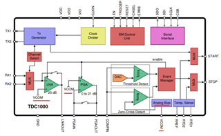
    Thank you for considering to use Texas Instruments.  The TX value depends upon the signal provided to CLKIN and your clock divider setting. Component Y1 which is part number ASEMB-8.000MHZ-LY-T provides 8MHz to the TDC1000.  The division factor of the clock divider can be programmed with the TX_FREQ_DIV field in the CONFIG_0 register.  There are some obstacles to measuring taller water levels than what is shown in the EVM user guide, but it might be possible for your application.  TIDA-00322 might be good starting place for figuring out how.

  • Hello PY YEN,

    Thanks for posting to the sensors forum! The circuit suggested for TIDA-00322 is optimized for 1MHz performance but should work fine for 2MHz operation as well. You can alter the values in the bandpass filter if you are not getting the appropriate signal at the COMPIN pin, but change should not be necessary since the filter is speced for up to 3MHz. There are no expected changes for the high voltage driving circuit as well.

    My recommendation would be to create this design in order to test this setup on your own tank. There can be some differences in performance depending on the tanks material so it is always good to try and use the same or similar tank you will use for your final application. The 2MHz transducer will provide a finer resolution for your measurements but please note that the higher the frequency the faster the signals attenuate since they cannot carry much energy. My recommendation to achieve a 1.5m distance is to incorporate a wave guide under the transducer. This helps keep the signal of the transducer concentrated and prevent it from spreading to maximize the detectable distance. This also  helps for instances if the tank is tilted and the wave guide also acts as a natural filter to improve signal to noise ratio.

    If you need a starting point you can use the TDC1000-C2000EVM and simply create the boost circuit for testing. I hope this helps!

    Best,

    Isaac

  • Thanks  for Isaac's  suggestion  and  now  I  certainly follow your suggestion to use TDC1000-C2000 EVM with high voltage drive circuit ( suggested from TIDA-00322EVM ) . 

    How about the waveguide ?  any suggested part no. of the suitable wave guide ?  how to combine and use the sensor and waveguide to test the water level ?  

    thanks for your help ~

  • Hello PY YEN,

    No worries, always glad to help out!

    We don’t have a part number for the waveguide, the waveguide is essentially an addition to the inside of the tank that fills along with the tank. Typically it can be made out of plastic. 

    It just needs to at least be the diameter of the selected transducer to allow the entire signal from the transducer to enter the waveguide and have holes at the bottom or along its length to ensure that liquid fills it along with the tank.

    The measurement is performed as normal, the waveguide just ensures increased stability and performance.


    Best,

    Isaac

  • Thanks  for your friendly reply  ,   it is  useful for  us .     thanks   again ~ 

  • Of course, let me know if you have any other questions I might be able to help out with!

    Best,

    Isaac

  • hello~   Isaac :  

    Excuse me ~  

      1. With the optimized and suitable circuit on the same water tank , how about the propagation distance  of  1MHz & 2 MHz sensor  ?   will 2MHz sensor propagate further than 1MHz sensor ??   

      2. If the sensor is enclosed with different material such as  metal  cover or  plastic cover   ,  will it affect the  propagation distance ? Will metal cover propagate further than plastic one ( while using the  same frequency sensor )  ?   

    thanks ~   

  • Hello PY YEN, 

    Let me help address your questions:

      1. With the optimized and suitable circuit on the same water tank , how about the propagation distance  of  1MHz & 2 MHz sensor  ?   will 2MHz sensor propagate further than 1MHz sensor ??   

    • It is difficult to define the sensing range of each system since they can depend on many factors such as, how the transducer is being mounted, the tank material, frequency and driving voltage along with others. This is why we typically recommend testing on as close of a system to your final product as possible. A 2MHz transducer will have a lesser propagation distance than a 1MHz transducer, meaning the 1MHz transducer would be able to travel farther than the 2MHz transducer.

      2. If the sensor is enclosed with different material such as  metal  cover or  plastic cover   ,  will it affect the  propagation distance ? Will metal cover propagate further than plastic one ( while using the  same frequency sensor ) ?

    •    Relating cover material with sensing range is not something we have really experimented with before. Typically, sensors with a cover are less sensitive compared to transducers that do not have covers. The benefit of covered transducers is that they are very robust for harsh environments.

    I hope this helps!

    Best,

    Isaac

  • Thanks  for   Isaac's reply  ~  it is very helpful for us  

    Is  there  any successful example to test the  water level up to 1.5m or 2m  by using TIDA-00322EVM  solution ??  we would  set this  distance for our  design target.     

    thanks ~   

  • Hello PY YEN,

    Glad to help out.

    I dont have a direct example myself, but I am aware that customers have been able to achieve larger distances than what was tested using the TIDA-00322 solution in our documentation. They achieved this by increasing the voltage being generated by the transducer in order to have enough sound pressure to have enough strength to reach the end of their tank and return back to the sensor, the only thing I am not sure of is the exact distance they were able to achieve. 

    Best,

    Isaac

  • HELLO~  ISAAC  :       

    Thanks for your  information   ~

    although   it is  a pity  that we have no opportunity to  know  the  actual detected water level .   

    thnaks  again   

  • Hello PY YEN,

    I agree, but no worries. Let me know if there are any other questions.

    Best,

    Isaac

  • Hello~   Isaac :  

    According to your opinion and experience,  what is the possible maximum limit  water level bu using 1 MHz  transducer and TIDA-00322 solution ??   Up to the present , we could not achieved  more than 90  cm water level .     

    thanks  ~ 

  • Hello PY YEN,

    Thanks for the info. Like I said its hard to define a distance because its dependent on a lot of factors like tank material/thickness, voltage on the transducer, transducer fov, and so on. 

    Have you tried using the waveguide in your tests to see if this helps you achieve a greater distance?

    I would also suggest perhaps looking at TUSS4470, this device has an improved dynamic range compared to the TDC1000. Perhaps this will help you increase the sensing range. The device can be used in a similar way to the TDC1000, the TUSS4470 can generate an interrupt when the echo generates a signal high enough to trigger a programmed threshold, similar to the TDC1000. Unfortunately, the TUSS4470 only goes up to 1MHz excitation for transducers and is not automotive qualified if that is a requirement for your application.

    Best,

    Isaac 

  • Hello~   Isaac: 

    Sorry to be  late   ~ 

    We are not yet  ready to test the  water level with a  waveguide .  maybe it deserves to try ~ 

    How far could the water level achieve by using TUSS4470  solution under the  same testing condtion and platform  ?    

    Thanks

  • Hello PY YEN,

    The waveguide should improve your performance due to the fact that it keeps your ultrasonic signals energy from dispersing all over the tank. As far as the TUSS4470 goes, the same disclaimer goes as the previous solution its hard to quantify due to all the other factors, but the nice part about TUSS4470 is that you shouldn't require a separate circuit to drive the transducer at a higher voltage. This device can handle up to 36V without additional components, and the dynamic range is much larger, supporting up to 90dB of gain compared to the 32dB given by the TDC1000. So overall its a better device and should see some improvements in your setup.

    Best,

    Isaac 

  • Hello   Isaac :   

    It is  glad to receive the  suggestion from you  ~  

    TUSS4470  solution  seems suitable and better than TIDA-00322 ,  especially in the  spec of driving voltage and  power gain.     We will study and  evaluate this  solution. 

    thanks again for your  kind help &  full support  ~        

  • Hello PY YEN,

    No worries glad to help out. Please let me know if there is any other help needed. Feel free to start a new post regarding TUSS4470 if the questions are regarding that device in specific it helps users find answers much easier if  have if they have a similar question.

    Best,

    Isaac

  • OK    Let's   find out the  TUSS4470 forum 

    Thanks again ~

  • Thank you as well PY YEN.

    Best,

    Isaac

  • HELLO~   Isaac  :

    In addition to TUSS4470  solution, is there any other solution better than TUSS4470 to detect long distance of water level with 1 MHz  sensor  ??

    or  TUSS4470  is the optimized solution for long distance application with 1 MHz  sensor  ??

    THANKS ~   

  • Hello PY YEN, 

    That is correct the TUSS4470 is the optimized solution for long distance measurements using a 1MHz transducer.

    Best,

    Isaac

  • thanks Isaac's answer  ~  

    many  thanks ~

  • HELLO~  ISAAC :  

    EXCUSE  ME  ~ 

    1.  TDC1000PW  IC    VDD  pin ,  now  we set 4.5 V ( by using 5V to 4.5 V   LDO  circuit ) ,   could we update to 5 V  for  VDD  pin ? 

    2.  The VCOM pin ,  now we set  2.25V ( by using voltage divider circuit ,  and the VDD  is 4.5V  )  ,   could we update to 5 V  for  VDD  pin  and  thus  VCOM is 2.5 V ??  

    Is there any  bad  influrence on the  test function  after these  voltage change ??   

    thanks  for your  help ~    

  • Hello PY YEN,

    1. VDD can be set to 5V or 4.5V, the max voltage for this pin is 6V.

    2. A voltage of 2.5V is acceptable for, in fact VCOM is usually recommended to be VDD/2.

    Increasing the voltage will generate a slightly larger pulse on the TX, but if you are using the same circuit as the TIDA then the UCC27531-Q1 can handle up to 27V continuous on the EN and IN pins so there is not much of a concern there. The VCOM is used as a reference voltage for several blocks inside the TDC1000, I dont think you will see much of a difference due to the change since VCOM is still equivalent to VDD/2.

    Best,

    Isaac