This thread has been locked.

If you have a related question, please click the "Ask a related question" button in the top right corner. The newly created question will be automatically linked to this question.

DRV5056: Temperature rise on the DRV5056

Part Number: DRV5056

Hi team,

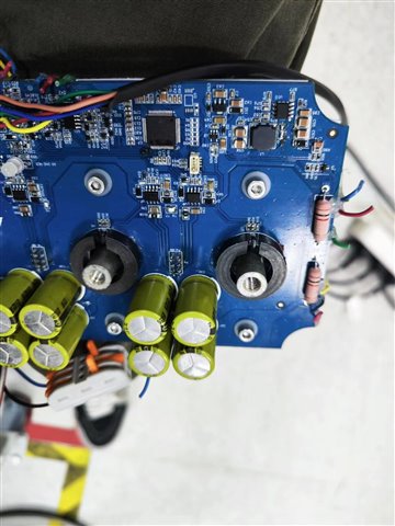
1, as shown in the figure, we use open-loop measurement to detect the current and then to calculate the magnetic induction strength B, we use B = µ0 * H (where µ0 is the vacuum permeability, H is the magnetic field strength generated by the wire), H = N * I / d (where the copper column can be considered as a single wire so N = 1, I is the current through the conductor, d is the magnetic ring opening distance). Is the calculation right?
2, on the DRV5056, I see this formula VOUT = VQ + B × Sensitivity(25°C) × (1 ( + STC × (TA ± 25°C))), does this mean that using this formula will be able to ignore the effect of temperature rise on DRV5056?
3, if we want to achieve the full temperature range, the maximum error of the test current within 3%, is it possible?

  • Zoey,

    Thank you for reaching out with your question.  The sensitivity temperature compensation (STC) of DRV5056 is intended to counter the negative temperature coefficient of NdFeB magnets which degrade at about -0.12%/C.  As the magnet and sensor change temperature together, STC will ideally correct for the change in magnetic field and produce a more stable output response.

    For sensors ending in the Zx suffix, there is a 0% STC value, which would probably be better suited to this application.  Where you are trying to measure the magnetic field produced by a current carrying trace.

    The field from a straight wire can be estimated as B = (µ0*I)/(2*pi*r)

    The challenge for this measurement is ensuring that the current you are measuring is strong enough such that the SNR of the measurement will produce useful results.  For instance, if measuring 1 A at a range of 0.65 mm (distance from sensing element to PCB surface), the field strength will be about 0.31 mT.  The input referred noise of the sensor is 0.2 mTpp when operated at 3.3V, so the quality of the current measurement may be less than ideal. 

    It will additionally be necessary to place the sensor in a location where the field is perpendicular to the surface of the PCB.  Directly above the wire the field will be parallel to the PCB surface.

    For measuring current, it may be more ideal to consider one of our magnetic current sensors:

    https://www.ti.com/sensors/magnetic-sensors/products.html#-3=Hall-effect%20current%20sensors&

    Thanks,

    Scott