- Ask a related questionWhat is a related question?A related question is a question created from another question. When the related question is created, it will be automatically linked to the original question.
This thread has been locked.
If you have a related question, please click the "Ask a related question" button in the top right corner. The newly created question will be automatically linked to this question.
Hello, all.
I've been using the LDC1101 eval board to evaluate a coil wrapped on ferrite. The nominal inductance of the coil is 30 uH. The parallel
capacitor is 220 pF. On some of the units, the data comes up pretty much as I expect; ~10Kohm, 27 uH, 2.07 MHz. (with no target).
On some of the other units, the response is wildly out of range; 13Kohm, 186 uH and 786 MHz. However, if I start the GUI's
active mode with the maximum target in place on those units, then the response is what I expect. My configuration settings are the same for all;
0x01=0x24
0x02=0xDB
0x03=0xF8
0x04=0x06
0x20=0x68
Has anyone had similar issues?
It's like something inside the device has railed, but there's never a sensor oscillation alarm in the GUI.
Thanks!
Karen
Hello Karen,
Thanks for considering to use Texas Instruments. What is your INTB_FUNC setting in register 0x0A? Do you observe this right after programming the registers or after power up or exiting from shutdown mode?
Hello Patrick,
Register 0x0A =0x00, always ... after start-up of the GUI, after loading the config file, or going in/out of active/sleep mode.
(although the letter is questionable; I think every time I go to the page to read the registers, the eval board puts itself
into sleep mode and then back into active mode autonomously).
Regards,
Karen
Hey Karen,
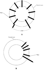
Not sure if you are using a toroid core or not, but the spacing between the turns (such as the bottom example in the figure below) could have an impact on the stray capacitance, which would affect the resonant point. Also if you have something with a high dielectric constant near or touching the coil, that could be having some impact as well. Does this occur at all in active mode whether the target is present or not?

Hi Patrick,
I'd call it a gapped toroid, though it's not a traditional shape. Can you suggest a way I might measure the stray capacitance? The core is potted, and I can't see the turns. I try to keep the eval board and the attached coil dangling off the bench, on top of a large piece of anti-static foam, so no, there's nothing near the coil. I have noticed that occasionally if I touch the coil/eval board I can get the appropriate response in the gui, but starting with the target is more consistent.
I'm puzzled, though, why any stray capacitance - presumably inherent in the winding itself - would produce two such drastically different results for what the eval board determines as L+RP.
Hey Karen,
An LCR meter might be helpful. I think in this case we would assume the stray capacitance is in parallel, thereby increasing the overall capacitance of the LC tank. If the capacitance you are using in the calculation is lower than reality, the sensor frequency will be lower than expected, and if the frequency detected is really low, then the inductance value will need to increase to justify the frequency provided in the calculation. However, there could still be something else going on, I need to consult with my colleagues and see if there may be any other explanation.
Karen,
Patrick is out today.
Is it possible to look at the sensor waveforms with an oscope and upload the images to this thread?
Based on your descriptions it might be helpful to look at the sensor waveforms when sensors are and are not behaving as expected .
Regards,
John
I can try that on Monday. High impedance scope probe or a 50-ohm-ish probe?
br,
Karen
Karen,
A high impedance probe.
It sometimes helps reduce parasitics to have a 1k resistor between the probe tip and the test point.
Regards,
John
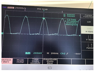
Here is a typical signal at R1 or R2 on the eval board, of a 'normal' one. Frequency looks right, amplitude is roughly half what I expected.
I was surprised it looks like a clipped sine wave ... is that expected?

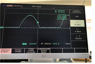
This is the same point for the odd ones. Frequency matches what the eval board says, and is correct for an inductance of ~175 uH

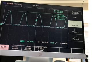
And this is what that same point looks like if I start the eval board with a maximum target

For the LDC1101 you should see a clipped sign wave. Have you had a chance to look at your coil with an LCR meter yet?
I don't have an LCR meter. I did measure them with a VNA, and will post that data once I find it again. I don't recall anything unusual.
For your evaluation are you using multiple EVM boards to evaluate your coils, or are you using a single evaluation board with all the coils?
Hello Karen,
So if I understand correctly, you are consistently seeing unexpected results for certain coils, while other coils consistently yield measurements you expect with the LDC1101EVM. Based on this, I think we need to reassess these coils on the vna. Can you provide a csv file with frequency, |Z|, and ∠Z for both a coil with expected behavior and a coil with unex? Alternatively, if you are unable to export a csv, could you take a picture of the smith chart with markers at a frequency in the inductive region, resonant frequency, and capacitive region? We think that your resonant frequencies for a normal coil vs an abnormal coil will likely be different. Consequently, the frequency range and parallel capacitance you specified for one coil may be adequate for one coil while not for the other.
Hi Patrick,
Yes, you've summarized it accurately. I can re-measure on the VNA, (next week after I finish some other temp testing.) One unfortunate thing is that the VNA i have only goes to 4 GHz, and I can't see the SRF. When I measured some of these coils previously, the SRF was in the 10-12 GHz range. I'll ask some of my colleagues if they have a network analyzer with a larger range.
Regards,
Karen