This thread has been locked.

If you have a related question, please click the "Ask a related question" button in the top right corner. The newly created question will be automatically linked to this question.

DRV421: Simulation Model

Part Number: DRV421
Other Parts Discussed in Thread: DRV411, TIPD184

Hi Support team,

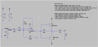
do you have a simulation model for DRV421? It would be great for LTspice. If not, could you tell me how I can simulation the output signal of Icomp1 and Icomp2? I tried to generate a current source of 250mA out from the Icomp2, but I don't know what to do with the Icomp2. I am currently simulating a external driver circuit using this chip. Thanks.

Regards,

Yutong

  • Hello Yutong,

    Unfortunately we do not have a model for this device.  I would simulate the output signal you would need to do the FETs with the r-on to give you a max Voltage of 4.2V with a 20Ω load or (210mA).  I got this from the datasheet.  So the combination of the Pfet and Nfet would be about 3.8Ω.  Now this is an H-Bride so you would ideally use both to get an output current.  Also this current is controlled by the magnetic field seen at the sensor location and is the feedback for the H-Bride.  Without this the loop would not work and you would only get a railed output.

    Can you show me in a schematic what you are attempting to do.

  • I am simulating the external current driver which can produce more current for the compensation winding

  • Hello Yutong,

    This is very similar to this design: https://www.ti.com/tool/TIPD184  Even thought the DRV411 is used with a hall sensor it still has a similar output structure to drive the compensation coil.

    Regards,

    Javier.

  • Hello Javier,

    I've already found this document, so I would like to use it in the simulation. Because a Zero-flux current sensor has a very different principal as the hall sensor, so I must make sure if the output current from the IC, together with the external OPA can produce enough current for my application or not. Thus the simulation. As I have an input of 0.25A, which is the maximum current the IC can produces, but it still doesn't creat enouth current at the output of OPA. So I ask if I think it in the wrong way, I mean, if it is so easy to just input a current source of 0.25A? But I don't know what comes out from the IC.

  • Hello Yutong,

    The output of the IC is a voltage the will be regulated to get you zero field at the sensor.  The output current will be limited from the H-Bride due to the FET on resistance and the voltage.  If you have a gain stage like the design I shared above the current is driven now by the output FETs.  The DRV421 only then regulates the voltage based of the field seen that in turn controls the current to place the field back to zero.  This voltage can drive a coil but is limited like I described above.  The feedback of the DRV411 and DRV421 through the compensation coil is the same and the output drive for the compensation coil are very similar if not the same.  

  • Hello Javier,

    I still have an another question about the circuit in the document TIPD184. What does the VSS mean? I would like to supply the circuit in +15V and -15V. As I understood, the VDD would be in this case +15V and VSS the -15V. But I am not sure if the VSS shall be equal to GND or the -15V in this case? Because it is also connected to the GND pin of the chip itself and the voltage regulator.

  • Hello Yuton,

    I see confusion.  So in this circuit you the lowest voltage is -15V which is VSS.  The 5V from the LDO is referenced to this VSS(gnd pin).  So VSS is the gnd(reference) point for the DRV411.  The DRV411 supply(VDD pin) and gnd(GND pin) will be below the GND of the board.

  • Hello Javier,

    I would like to talk about the application in DRV421 which I would use later. DRV411 is not considered. I understand that -15V would be the VSS. The question is now if you connect the VDDpin to 5V and GND pin to -15V, there will be a voltage drop from 20V, which is far beyound the tolerance of the chip. Or you mean the 5V at this case is referenced to VSS so it is actually at a level of -10V? Because in the data sheet the supply voltage range is 3.0 V to 5.5 V, how can this work if you actually have a negative voltage on VDD?

  • Hello Yutong,

    The voltage on the DRV411 is relative to its GND pin.  Not GND itself.  So below are Voltages referenced to GND.  

    VDD = 15V referenced to GND

    VSS = -15V referenced to GND

    5V = -10V referenced to GND

    GND pins on DRV411 are connected to VSS so all the voltages for the DRV411 are referenced to VCC and not GND.   So the voltage at the DRV411 is still 5V.