This thread has been locked.

If you have a related question, please click the "Ask a related question" button in the top right corner. The newly created question will be automatically linked to this question.

DRV401: About probe excitation and closed-loop accuracy

Part Number: DRV401
Other Parts Discussed in Thread: DRV411

Hi expert,

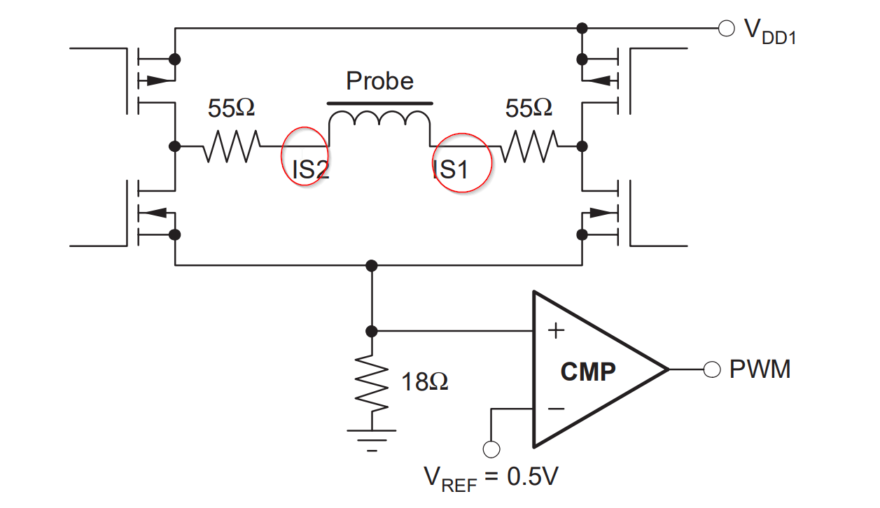
I'm trying to understand how DRV401 can co-work with my magnetics and probe design.

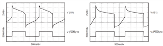
DRV401 offers IS1/IS2 as probe interfaces however it doesn't mention how the probe should be like, only below probe current waveforms are shown.

My three questions are:

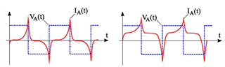
①how this probe (saturable inductor as normal) is excited and biased by DR401? I cannot image what the excited source is like through the 50% duty-cycle IS1 waveform in datasheet.

②Is the PWM duty cycle or width, strictly proportional to primary side input current? And how to ensure this principle?

③I have learned that closed-loop fluxgate can achieve very high accuracy, however no claimed accuracy found in datasheet, TI also has closed-loop AFE DRV411, very similar with DRV401 and the only difference is the probe (fluxgate or hall element), the accuracy is claimed 0.2% max in the first page, I'm just confused what's the accuracy differences between these two schemes? 

As in my understandings, the closed-loop current transformers structure are totally the same, the key point should be the probe open-loop accuracy, which can more accurately report zero-magnetic flux, correct or not?

Thank you very much for your kind help and explanations.

  • Hello User,

      This is the image of the drive of the probe with the PWM controlling when the H-Bridge switches direction.  There is more explanation in the datasheet in the "MAGNETIC PROBE (SENSOR) INTERFACE" section.

    ② During normal operation this will be at 50% duty with the width dependent on the saturation of the probe.  This does not have anything to do with the frequency of the Primary.  During some time when the Primary changes this duty cycle will change for a cycle while the compensation current adjust to the compensate for the primary.

    ③  The difference between the two is more due to the magnetic field measurement.  Both will bring the field at sensing location to zero.  The flux-gate has better noise and offset and this is the cause of it being more accurate.

  • Thanks very much Javier, please allow me to ask some further questions according to your answers.

    About ①, I go through "MAGNETIC PROBE (SENSOR) INTERFACE" section, the detailed confusing point is about how the IS waveform is like such.

    In common understandings, the saturable inductor should have smaller inductance as current increases, with 50% duty-cycle voltage across the probe, the voltage/current waveforms are supposed below. It's different from what we see in DRV401 datasheet. 

     (left is when Ip=0, right is when Ip>0)

    About ②, I can fully understand the principle you described, however what I mean for "strictly proportional", stand for relationships between Ip and duty, wonder if they are linear or totally non-linear?

    For example, if Ip=0→duty=50%, Ip=1A→duty 55%, Ip=2A→duty 60%, this is linear.   

  • Hello,

    For ① the voltage will be like a square wave but the current will peak after as the probe (inductor) becomes saturated then the current increases to the point that the comparator trips.  When an external field is applied to the inductor it shifts how soon the inductor becomes saturated.  During normal opearation the compensation coil or the transformer effect will always bring this back to 50%.

    ② For this the device should always return to 50%  What is linear is the compensation coil current as this is what is brining it back to 50% so at steady state they PWM duty should return to 50% no matter what the IP is.  Granted there is some small change as the overall loop gain is a factor but this should be seen at 50%.

    Regards,

    Javier