This thread has been locked.

If you have a related question, please click the "Ask a related question" button in the top right corner. The newly created question will be automatically linked to this question.

AFE3010: AFE3010 application

Part Number: AFE3010

Hello,

There are some questions about AFE3010:

1.  SCR (Pin 6)

    -  What is the output voltage range ? What is the factor affecting the output voltage?

    -  What is the duration (ms) of the output inrush pulse?  What is factor affecting the duration?

2. ALARM (Pin 7):

   -  If there is current leakage detected, the function “Self-Test” will stop?

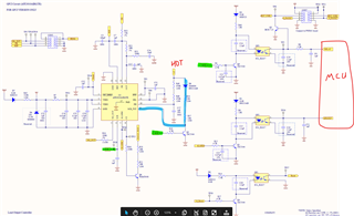
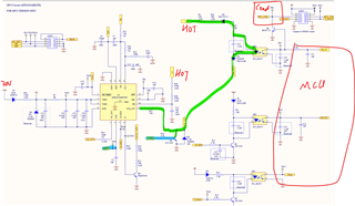
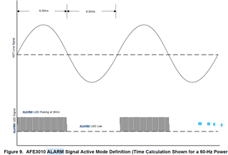
   -  If there is current leakage detected, the “ALARM” pin will keep as below capture? Any method to resume “ALARM” pin to logic LOW except re-power up? 


3. SCR_TST (Pin 9):

    - According to datasheet application circuitry recommended to use 51kR, 1% for R11.  If our product application with power supply 120Vac, 60Hz or 240V,60Hz, what is the recommended value and tolerance for R11?

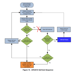
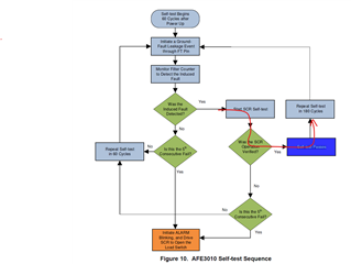
4. Datasheet : "7.3.7 Self-test function" : The AFE3010 performs two different types of self-test : periodic self-test and continuous self-test

    -  For the “Periodic Self-Test” block diagram, should we refer to “Figure 10”?

    -  For the “Periodic Self-Test” block diagram, should we refer to “Figure 10”?

5. Datasheet : 


    - Any requirement for VDD rising time? (i.e. the VDD rising time should be faster than specific IO?)

  • Hello valued engineer,

    I am looking this over and will respond shortly.

    Sincerely,

    Peter

  • Hello valued engineer,

    1. SCR pin is a current driver. The exact voltage when pin is activated depends on the load resistance it drives, specifically the SCR gate and any resistance in-series with it. When firing the SCR, the time duration of the pulse will at least be one positive half cycle. Maximum duration will be two full line cycles. Cycle length is determined by measuring the zero crossings at the PH pin.
    2. Yes, if device detects leakage current it drives SCR and blinks ALARM indefinitely until device is power cycled or RESET. It will stop performing self test. If you want to RESET device (resets internal fault counter), then you can use either PTT or SWOPEN (see Figures 11-14) in datasheet. If you want to reset device without it firing the SCR from the self test, you have to provide a 55ms signal to SWOPEN pin (see the tD4 time specification in electrical characteristics table in datasheet).
    3. The tolerance for R11 does not have to be tight, +/-10% is fine. Also the line voltage does not affect the required resistance of tolerance here. However, the larger line voltage does mean you need increase power dissipation in R11. I should note that R11 can actually be increases up to 68 kOhm, which will help decrease power dissipation required. Power dissipation is based on that SCRTST is clamped to 20-V every positive line cycle and floating during negative cycle due to D2. I have provided a power dissipation calculator for R11 (and other resistors) for higher line voltages. With a 68-KOhm R11, you could use a 3/4W resistor rating.
    4. Figure 10 describes sequence for the periodic self test. The continuous tests are described in 7.3.7.2..
    5. The rising time should be limited to ~10ms. However, a final validation of power up trip times should be performed because of system level differences. The trip times at power up scenarios is affected by rising time because this delay will be included in the overall trip time. You also do not want the RC time constant to be too fast because VDD can collapse more easily during failure condition when one of the diodes in the rectifier (D1) are opened/shorted. The VDD resistors and capacitor shown in the datasheet did provide compliant trip times at power up over temperature and stable VDD during D1 failure conditions.
    6.  1440.AFE3010 BOM_calculations.xlsx

    Sincerely,

    Peter

  • Dear Peter,


    For SCR pulse width, is the SCR pulse width different in the following 3 cases?  Can you tell me more about it? 
    - self test PASS & NG
    - Current leakage detected
    - Device reset (ie. reset with PTT)

    Best regards.

    Lin Yu

  • Hello Lin,

    For a self test pass, there is no SCR pulse.

    For a ground fault (or neutral to ground fault) detected, the SCR pulse will be at least one, positive, half-cycle.

    For a device reset and subsequent self-test pass, the SCR pulse will be at least one, positive, half-cycle.

    For an "open solenoid" self-test fail (see section 7.3.7.2), SCR pulse will be two full line cycles.

    For all other self test failures, the SCR pulse will be at least one positive, half cycle.

    Sincerely,

    Peter

  • Dear Peter,

    Thanks for your reply.

    There are also the following questions:

    1. According to the application circuit (figure 15), is the solenoid on/off when the SCR self test (output High)? 

    2. When SEL=floating, The SCR self test disable. Is the path below disabled?


    3. When SEL=floating, The SCR self test is disabled. Will UL943 authentication be affected?

    Our product requirements conform to UL943 class A, I wonder if it has any impact

  • Hello Lin,

    1. The solenoid is not affected during the SCR self test because the test occurs during the negative line cycle.

    2. Correct.

    3. Disabling the SCR self test will affect UL 943 certification. It is not a recommended mode of operation. The other valid SEL mode is when you actually set SEL to 2.5V with a 500kOhm pull-down resistor and use ALARM pin to drive a redundant SCR. In this dual-SCR mode, the SCR self test is still enabled and will be testing the SCR and/or solenoid corresponding to the SCR pin.

    Sincerely,

    Peter

  • About your reply " The solenoid is not affected during the SCR self test because the test occurs during the negative line cycle."

    a. Do you mean the AFE3010 SCR(pin6)output High and the triac doesn't turn on during the self test ? 

    b. Can you show me  how the "SCR self test sequence" works on hardware?  

    Is this process "AFE3010 SCR output HIGH -> Triac switch ON -> SCR-TST detect LOW -> PASS " ?


  • Hello Lin,

    The SCR self-test is not technically turning on the SCR. During the self test, the SCR_TST pin becomes a current source and injects current into SCR anode. This causes the SCR anode and gate voltages to rise. The device turns on SCR to see that these raised voltages drop back down to 0V. If this happens, then devices determines the SCR is still working.

    Sincerely,

    Peter

  • Dear Peter,

    1. "The device turms on SCR to see ..."   Do you mean AFE3010 (SCR pin output high)turms on SCR (triac) ?
    2.  For figure 15, Can I use transisitor instead of SCR  ?

    Best regards,

    Lin

  • Hey Lin,

    Yes by “device turns on SCR” I mean that the SCR pin starts driving current to turn on SCR.

    I suppose you could use a transistor, but please validate this to make sure the transistor can pull enough current to actuate solenoid (if using this) and that SCRTST can still perform the SCR self test (SEL=GND) if you choose to enable this self test.

    Sincerely, Peter

  • Dear Peter,

    Thank you for your reply. Here I have some more questions as below .

    1.  " Yes by “device turns on SCR” I mean that the SCR pin starts driving current to turn on SCR", Does it mean that the SCR pin will start driving current to turn on SCR during each self test ?

    2. Do you think have any problem on below circuitry design with transisitor instead of SCR? or do you have any other sugguestion?


    Best regards.

    Lin Yu    

  • Revised circuitry :

  • Hello Lin,

    1. SCR turns on and sources current when it detects fault condition or fails self test. During self-test the SCR is technically turned for a short time and with low turn-on current, but this occurs during the negative line phase and thus current should not flow through solenoid given that there is a reverse polarity blocking diode, D4.

    The SCR is turned on to see if SCR will pull down the SCRTST node, which get biased during negative line phase.

    2. I think using a transistor versus an SCR should theoretically still work the same, but please test this on bench with AFE3010EVM. And make sure you have the biasing resistors R37, R26, R4, R34 adjusted accordingly 

    Sincerely,

    Peter

  • Dear Peter,

    Thank you for your reply,

    Last question,

    As you can see, There is  C11 in  typical application ,but not in GFCI application, is it necessary? If so, what is the range  of value?

    Best regards.

    Lin Yu

  • Hey Lin,

    You definitely want to use the schematic shown in Figure 15, so yes you probably will need a C11. I recommend a typical value of 2.2nF in Table 5 of datasheet. This capacitance is helpful in keeping the SCR stable from noise or high voltage surges, but it can't be too high (~ 10nF; exact value should be validated for your system) because it will interfere with the SCR self test.

    Sincerely,

    Peter

  • Dear Peter,

    Here I have some questions as below .


    1. Does SCR_TST need the external power source voltage higher than 20V for normal operation? e.g If figure 15 remove D2, will the self test pass?

    2. Using ALARM port for MCU detection to idendify different mode (self-test pass/fails ,H-G,N-G fault), Do you think it will be worked?

    3. When SEL=Low and /SW_OPEN=Low, what is the ALARM port output signal for below situation.
         - At power up /first self-test :?
         - First self-test pass : ?
         - First self-test fail : ?
         - H-G or N-G fault : ?
         - Reset by PTT:?

  • Hey Lin,

    1. For SCR's self test (which is only done when SEL=GND), the self test will only pass if SCR_TST is connected to the anode of an SCR and that voltage is a half-rectified signal that goes between >=20V and 0V (with respect to AFE3010 GND) and the signal has same frequency as voltage at PH pin. 

    2. With SWOPEN =float, this will not work because the subsequent actions to a ground fault and a self-test fail are the same: SCR fires and ALARM blinks. In order to digitally distinguish between self-test fail and ground fault you would need to actually be monitoring OUT pin to look for out-of-range signals (Vout > 2.75V or Vout < 2.25V) that would indicate device is detecting a true ground fault.

    Now if SWOPEN is always LOW, then you could use distinguish between a self-test fail and ground fault by only looking at ALARM pin as shown in Table 3 of datasheet.

    The self-test pass when pressing PTT would present another condition, because once PTT is pressed and device passes the single, subsequent self-test, the AFE3010 will fire SCR once as shown in Figure 11.

    3.  For SEL=GND and SW_OPEN = GND, 

    At power up and device passes first self-test, ALARM is on with no blinking.

    At power up and device fails first self-test, SCR fires and ALARM blinks.

    With a H-G or N-G fault, SCR fires and ALARM is on with no blinking.

    If PTT is pressed and device had previously failed a self-test/detected fault AND AFE3010 passes subsequent self-test, THEN SCR is fired and ALARM will stop blinking and go back to constant on.

    If PTT is pressed and device had previously failed a self-test/detect a fault AND AFE3010 fails subsequent self-test, THEN ALARM will remain blinking.

    If PTT is pressed and device had not previously failed a self-test AND AFE3010 passes subsequent self-test, THEN SCR is fired and ALARM will remain ON.

    If PTT is pressed and device had not previously failed a self-test AND AFE3010 fails subsequent self-test, THEN ALARM will begin blinking. (This is a very rare occurrence).

    Sincerely,

    Peter

  • Dear Peter,

    Thank you for your reply,  and I have more question as below,

    3.  For SEL=GND and SW_OPEN = GND, 

    - At power up and device passes first self-test, ALARM is on with no blinking. 

         [Lin] Is it on 250ms?

    - At power up and device fails first self-test, SCR fires and ALARM blinks.  

         [Lin] Is the blink frequency 0.5Hz ?

    - With a H-G or N-G fault, SCR fires and ALARM is on with no blinking.  

         [Lin] Does  "ALARM is on " mean ALARM output 3KHz square wave?

    - If PTT is pressed and device had previously failed a self-test/detected fault AND AFE3010 passes subsequent self-test, THEN SCR is fired and ALARM will stop blinking and go back to constant on. 

         [Lin] Does "go back to constant on" mean the ALARM  output LOW?

    If PTT is pressed and device had previously failed a self-test/detect a fault AND AFE3010 fails subsequent self-test, THEN ALARM will remain blinking.

         [Lin] What is the blink frequency ?

    Best regards.

    Lin.

  • Hey Lin,

    My apology for the delay.

    3.  For SEL=GND and SW_OPEN = GND, 

    - At power up and device passes first self-test, ALARM is on with no blinking. 

         [Lin] Is it on 250ms?

         [PI] No. For SEL=GND and SW_OPEN=GND, at power up and device passes first self-test, ALARM is constant on. So whenever SW_OPEN is pulled low to GND, ALARM will always be constant on (not blinking) unless there is a self-test failure.

    - At power up and device fails first self-test, SCR fires and ALARM blinks.  

         [Lin] Is the blink frequency 0.5Hz ?

         [PI] f AFE3010 does not pass a self test, the ALARM blinks with ON and OFF times of 60 cycles. So on 1 second and off 1 second repeatedly for 60-Hz lines

    - With a H-G or N-G fault, SCR fires and ALARM is on with no blinking.  

         [Lin] Does  "ALARM is on " mean ALARM output 3KHz square wave?

          [PI] When ALARM is ON, the output is always a pulse-width modulated square wave of 3 kHz and 50% duty cycle. The PWM helps save power as it it not necessary to provide a constant DC signal as the human eye cannot discern the difference.

    - If PTT is pressed and device had previously failed a self-test/detected fault AND AFE3010 passes subsequent self-test, THEN SCR is fired and ALARM will stop blinking and go back to constant on. 

         [Lin] Does "go back to constant on" mean the ALARM  output LOW?

          [PI] No. This means ALARM will go back to remaining constantly on (constantly providing 3 kHz signal to LED) because SW_OPEN is LOW. If SW_OPEN was released and allowed to float, then ALARM would stop driving LED (go low).

    If PTT is pressed and device had previously failed a self-test/detect a fault AND AFE3010 fails subsequent self-test, THEN ALARM will remain blinking.

         [Lin] What is the blink frequency ?

          [PI] ON for 60 line cycles and OFF for 60 line cycles (0.5 Hz for 60 Hz line voltages).

    Sincerely,

    Peter

  • Dear Peter,

    Thank you for reply, More question as below.

    1. For SW_OPEN = GND and SEL = GND,
         a. After power up and first self-test, What is the ALARM output signal for subsequent  self-test pass/fail ?

         b. For the table 3, Is the ALARM output same signal for H-G fault and power up/first self-test?

         c. Can use ALARM port for MCU detection to idendify different mode (power up,first selft-test,subsequent self-test pass/fails ,H-G,N-G fault)?

    2. For SW_OPEN = float and SEL = GND,

         a. what is the ALARM / OUT pins output signal  for below situation.

    Situation OUT (OK) OUT (NOK) ALARM (OK) ALARM (NOK)
    At power up/first self test        
    GFCI IC Self test
    (every 180 cycles)
           
    Current leakage(4~6mA)        
    IC reset (by PTT)        

    Best regards.

    Lin

  • Hey Lin,

    1. For SW_OPEN = GND and SEL = GND,
         a. The ALARM will go constant on. If device fail self test at any point, then ALARM blinks.

         b. No. If SW_OPEN=GND, then ALARM only blinks for a self-test fail. 

         c. With SW_OPEN=low, you could use ALARM to distinguish between a ground fault and a self-test fail. But you would need to be monitoring SCR to see when the fault even occurred. The other option is to have SW_OPEN floating, and once SCR is fired, then pull SW_OPEN pin low to see if ALARM goes constant high or continues to blink (see difference between Figures 13 and 14 in datasheet).

    2. For SW_OPEN = float and SEL = GND,

         a. what is the ALARM / OUT pins output signal  for below situation.

    Situation OUT (OK) OUT (NOK) ALARM (OK) ALARM (NOK)
    At power up/first self test  n/a n/a  Alarm blinks once because device passes first self test. Alarm blinks at 0.5Hz indefinitely because self test was failed.
    GFCI IC Self test
    (every 180 cycles)
     Single, short downward pulse (due to FT) on Vout that causes device to pass self test. See Figure 17  The self-test pulse (due to FT) last entire half-cycle because device cannot detect it due to system damage.  Nothing because device passes self test.  Alarm blinks at 0.5Hz indefinitely because self-test was failed.
    Current leakage(4~6mA)  Sinusoid between 2.75V and 2.25V. See Figure 17.  Sinusoid >2.75V and <2.25V until SCR is fired and load switch opened. See Figure 19.  Nothing. Alarm blinks at 0.5 Hz indefinitely because the 5mA leakage caused a fault detection.
    IC reset (by PTT)  Single, short downward pulse (due to FT) on Vout that causes device to pass self test. See Figure 17 The self-test pulse (due to FT) last entire half-cycle because device cannot detect it due to system damage.  Nothing because device passes PTT self test.  Alarm blinks at 0.5 Hz indefinitely because device failed self-test.

    Sincerely,

    Peter

  • Dear Peter,

    Thank you very much, Can you fill up the output signal for below situation?

    1. For SW_OPEN = float and SEL = GND,

    Situation SCR (OK) SCR (NOK) OUT (OK) OUT (NOK) ALARM (OK) ALARM (NOK)
    At power up/first self test ?? ?? n/a n/a Alarm blinks once because device passes first self test. Alarm blinks at 0.5Hz indefinitely because self test was failed.
    GFCI IC Self test
    (every 180 cycles)
    ?? ??  Single, short downward pulse (due to FT) on Vout that causes device to pass self test. See Figure 17  The self-test pulse (due to FT) last entire half-cycle because device cannot detect it due to system damage. Nothing because device passes self test.  Alarm blinks at 0.5Hz indefinitely because self-test was failed.
    Current leakage(4~6mA) ?? ?? Sinusoid between 2.75V and 2.25V. See Figure 17. Sinusoid >2.75V and <2.25V until SCR is fired and load switch opened. See Figure 19. Nothing. Alarm blinks at 0.5 Hz indefinitely because the 5mA leakage caused a fault detection.
    IC reset (by PTT) ?? ?? Single, short downward pulse (due to FT) on Vout that causes device to pass self test. See Figure 17 The self-test pulse (due to FT) last entire half-cycle because device cannot detect it due to system damage. Nothing because device passes PTT self test. Alarm blinks at 0.5 Hz indefinitely because device failed self-test.


    2.  For SW_OPEN = GND and SEL = GND.

    Situation SCR (OK) SCR(NOK) ALARM (OK) ALARM (NOK)
    At power up/first self test
    GFCI IC Self test
    (every 180 cycles)
    Current leakage(4~6mA)
    IC reset (by PTT)

    Best regards,

    Lin

  • Hey Lin,

    I need to correct something from my previous posts and that is: for SW_OPEN=floating, ALARM will remain off after detecting a ground fault and ALARM will only blink if device fails a self test as per Table 3 of datasheet. Thus, you absolutely can distinguish between a self-test fail (end-of-life condition) and a ground fault by noting the behavior of ALARM pin. I have made the correction in the tables below. I am very sorry for the confusion.

    1. For SW_OPEN = float and SEL = GND,


    Situation SCR (OK) SCR (NOK) OUT (OK) OUT (NOK) ALARM (OK) ALARM (NOK)
    At power up/first self test Small, short pulse 60 cycles after power up during negative phase indicating passing SCR self test. See Figure 10 of datasheet. SCR is fired indicating device failed initial self test. Trip time is 5x 60 cycles for periodic self test failure and ~100ms for a continuous self test failure per section 7.3.7 of datasheet. n/a n/a Alarm blinks once because device passes first self test. See Table 3 of datasheet. Alarm blinks at 0.5Hz indefinitely because self test was failed.
    GFCI IC Self test
    (every 180 cycles)
    Small, short pulse every 180 cycles during negative phase indicating passing SCR self test. See Figure 10 of datasheet. ^Same as above.  Single, short downward pulse (due to FT) on Vout that causes device to pass self test. See Figure 17  The self-test pulse (due to FT) last entire half-cycle because device cannot detect it due to system damage. Nothing because device passes self test.  Alarm blinks at 0.5Hz indefinitely because self-test was failed.
    Current leakage(4~6mA) SCR fires approximately 150 ms after current leakage started. N/A Sinusoid between 2.75V and 2.25V. See Figure 17. Sinusoid >2.75V and <2.25V until SCR is fired and load switch opened. See Figure 19. ALARM remains OFF per Table 3 of datasheet. Alarm blinks at 0.5 Hz indefinitely because there was a self-test fail.
    IC reset (by PTT) Device performs a periodic self-test and if device passes periodic self test, SCR fires once. See Figure 11. Device performs a periodic self-test and if device fails periodic self-test, SCR does NOT fire. See Figure 12. Single, short downward pulse (due to FT) on Vout that causes device to pass self test. See Figure 17 The self-test pulse (due to FT) last entire half-cycle because device cannot detect it due to system damage. Nothing because device passes PTT self test as per Figure 11 of datasheet. Alarm blinks at 0.5 Hz indefinitely because device failed periodic self-test.


    2.  For SW_OPEN = GND and SEL = GND.

    Situation SCR (OK) SCR(NOK) ALARM (OK) ALARM (NOK)
    At power up/first self test Same as SW_OPEN=float Same as SW_OPEN=float ALARM goes ON and stays ON after power up, per Table 3 of datasheet. For a self-test failure, ALARM will blink, as per Table 3 of datasheet.
    GFCI IC Self test
    (every 180 cycles)
    Same as SW_OPEN=float Same as SW_OPEN=float ALARM is always ON, per Table 3 of datasheet. For a self-test failure, ALARM will blink, as per Table 3 of datasheet.
    Current leakage(4~6mA) Same as SW_OPEN=float Same as SW_OPEN=float ALARM is always ON, per Table 3 of datasheet For a self-test failure, ALARM will blink, as per Table 3 of datasheet.
    IC reset (by PTT) Same as SW_OPEN=float Same as SW_OPEN=float ALARM is always ON, per Table 3 of datasheet For a self-test failure, ALARM will blink, as per Table 3 of datasheet.
  • Dear Peter,

    Thank you for reply, 

    I want to use below method (SW_OPEN = float) for MCU detection to idendify different mode (self-test fail ,H-G,N-G fault), this method is easy to achieve.

     c. With SW_OPEN=low, you could use ALARM to distinguish between a ground fault and a self-test fail. But you would need to be monitoring SCR to see when the fault even occurred. The other option is to have SW_OPEN floating, and once SCR is fired, then pull SW_OPEN pin low to see if ALARM goes constant high or continues to blink (see difference between Figures 13 and 14 in datasheet).

    More question as below.

    1. What is the duration of the SW_OPEN pull LOW ? 

    2. Does "ALARM goes constant high" mean H-G,N-G fault ? 

    3. Does "ALARM continues to blink" mean self-test fail? 

    4. Could use SW_OPEN as reset pin as well?


    Best regards.

    Lin

  • Hey Lin, 

    I am looking into this and will respond shortly.

    Sincerely,

    Peter

  • Hello Lin,

    To distinguish between a self-test fail (EOL condition) and a ground fault, there are two options:

    A. SWOPEN = float. Constantly monitor SCR or load switch. If SCR is fired (or load switch opened), then monitor ALARM for ~2 seconds. If ALARM is blinking at 0.5Hz, then there is an EOL condition. If ALARM is not blinking, then it was a ground fault. This assumes that activating SCR pin opens the load switch.

    The only exception to make for this option is when PTT/SW_OPEN is being pressed low because a self-test is performed when PTT/SWOPEN is pressed. If this self-test passes, then SCR is fired (Figures 11 and 13 of datasheet). If the self-test does not pass, then SCR does not fire but ALARM does blink (Figure 12 of datasheet).

    B. Second option is as you describe. Once SCR is fired, pull SW_OPEN low and monitor ALARM for about 1 second to see if goes constant high (ground fault) or continues blinks (EOL condition). Then release SW_OPEN.

    In short, I would just recommend using option A as it requires the least amount of code/hardware.

    Here are the answers to your questions:

    1. The duration to pull SW_OPEN low has two timing specifications (tD2 and tD4, see electrical characteristic section 6.5 of datasheet). tD2 is the amount of time to hold SW_OPEN low in order for device to fire SCR and reset internal fault counter. tD4 is the amount of time to hold SW_OPEN low to reset internal fault counter without firing SCR.

    2. If SW_OPEN is low, ALARM will be constant high always unless an EOL condition is detected.

    3. If SW_OPEN is low, and an EOL condition is detected, ALARM will blink at 0.5Hz.

    4. Yes, you can use SW_OPEN to reset device (reset the internal fault counter) if device detected a ground fault or failed a self-test (see Figures 13 and 14 of datasheet).

    Sincerely,

    Peter