This thread has been locked.

If you have a related question, please click the "Ask a related question" button in the top right corner. The newly created question will be automatically linked to this question.

TMCS1101: Reading TMCS1101 output

Part Number: TMCS1101
Other Parts Discussed in Thread: TMCS1100, INA225

I am trying to use TMCS1101A3B-Q1 to measure 24VAC current. The typical current I care about is 150mA to 400mA, sustained over long periods of time. The load is a 24VAC solenoid for an irrigation valve (350mA inrush, 190mA holding, give or take). I mostly only care to know 1) if no current is seen for a few seconds, or 2) if current is above or below the 150-400mA range for a few seconds.

With no current I expect the output signal at 1.65V with +/9mV. What I actually see is 1.731V with +/-59mV variance.

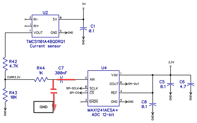
Besides that, I see a spike every time I read from my ADC (MAX1240).

The layout around my TMCS1101 looks like this:

There is no copper on any layer left or right of the TMCS1101 for at least 5mm. The ADC is 30mm away (not shown). The nearby ICs are optocouplers. It's a 4 layer board with both internal layers uninterrupted GND and power is routed on the outer layers. There are no components on the back.

With no current, this is what I see:

 (larger)

The spikes correspond to when I read from the ADC (30Hz in these pics). The rest of the noise jumps about +/-59mV every ~3.5ns, presumably when the TMCS1100 integrator propagates a new signal to the output.

With 44mA of current:

 (larger)

The low frequency here is 60Hz, so it seems the sensor is reacting to the 24VAC 44mA load. However, the output is so noisy I don't think it is usable in this state, also you can see it's quite a bit higher than 1.65V.

My probes are calibrated. The probe GND is a ground spring. GND and signal are taken at the sensor pins. The 3.3V supply voltage is stable, also measured at the sensor. There is 10uF bulk capacitance, plus 4.7uF by the ADC. The TMCS1101 and ADC have 0.1uF decoupling.

My initial test had the TMCS1101 2mm from the ADC. I moved it 30mm away hoping to remedy the spikes. It didn't (shown above) but trying that did mean that I see the same behavior with two different TMCS1101 ICs.

1) Is what I'm seeing typical? (noisy output, offset with no current is not at 1.65V)

2) Is TMCS1101 a bad fit for my use case? Should I be looking at INA225 or something else? My 3.3V and 24VAC do not share GND.

3) What do I need to do to have a usable design?

I could RC filter the output signal. Is that recommended and/or typically needed? What R and C values would be appropriate given my use case for an irrigation valve described above? Filtering wouldn't help with the offset being so much higher than 1.65V.

Should I do anything else? I could put slots left and right of the sensor.

  • Hello Nathan,

    I think you are seeing some noise for some of your measurements from the TMCS1101.  See this document https://www.ti.com/lit/an/sboa518/sboa518.pdf on section 4.2 it discusses the noise.  The reason for no current output voltage I cannot explain as the error could come from an external magnetic field also described in the application note I mentioned.  So the output noise or variation could be from an external field or noise.  For earth magnetic field I would expect a variation of about +/- 20mV but should not vary that much if not moving.  

    1) Is what I'm seeing typical? (noisy output, offset with no current is not at 1.65V)

    I believe the variation is noise but I cannot explain the variation with no current.  If this is measured with the ADC then you may need a capacitor for the ADC.  If you place an RC for the ADC please use a resistor larger than 100Ω.  This will eliminate any issue if you use a capacitor larger than 1nF which is max capacitive load.

    2) Is TMCS1101 a bad fit for my use case? Should I be looking at INA225 or something else? My 3.3V and 24VAC do not share GND.

    You cannot use the INA225 as the voltage cannot go below its GND pins.  I would suggest the TMCS1101 and calibrate the offset point and add the RC filter.

    3) What do I need to do to have a usable design?

    I think adding an RC filter and the values will be based on two things the frequency you need and how often you sample.  A larger capacitor will take longer to charge to you want to make sure the capacitor fully charges before the next sample.  This should eliminate the most of the noise.  

  • Dang, I didn't see that document previously. It is very helpful, thanks! I searched the internet for things like "TMCS1101 noise" and turned up little. I'll be more careful about looking in the right place next time.

    Looks like 1K ohm and 300 nF RC filter would give me a cutoff at 530 Hz. That seems OK for a 120 Hz sample rate of 24VAC @ 60 Hz.

    I'm using TMCS1101-A3B. Would I be better off using A4B @ 5V considering the current I care about is in the 150-400mA range? Bummer A4 isn't 3.3V.

    After filtering if I still have the offset, I guess I'll just compensate for it. The sensor's range is much higher than I need anyway.

  • Hello Nathan,

    Sorry the document was hard to find.  We have most of the documents in the technical documentation under application notes.  I am not sure if the title would have led you to the document.  I would use the 5V and if going to an ADC with 3.3V use a divider or if you have a reference you could use the TMCS1100 and just clip the output to 3.3V.

    Regards,

    Javier

  • Thanks Javier! I will give the below a try. Please let me know if something could be improved! Slight smile

  • Nathan,

    I have never AC coupled an input directly to an ADC.  I need to look at how this will impact the SAR plus there is no DC bias.  Do you need to AC couple?  Also normally in the input capacitor to GND commonly known as a charging bucket.  I know the basics but we have some tools on the input stage of a SAR ADC.

    If you don't need to AC couple I would remove C7 and pace a 16pF*20 = 320pF capacitor to GND (could be larger as you have a slow bandwidth you are sampling)

    For more information on the ADC see these training video:  https://www.ti.com/video/series/analog-to-digital-converters-adcs.html

  • Thanks for the video link, I'll watch it ASAP, later today.

    Maybe I misunderstand, but I don't think there is AC coupling in my schematic? It's 3.3VDC at C7. IN+/- is 24VAC, the TMCS1101 outputs 0-5VDC, the voltage divider scales to 0-3.3VDC, that is RC filtered, then to the ADC.

    Do you mean keep what I have but use a capacitor to block half of the AC component before the TMCS1101?

    Ultimately I just want to read the current of a 24VAC solenoid in the range of ~100-400mA. Sweat smile I'm not married to any of what I have, I'm happy to throw it out and do something else.

  • Hello Nathan,

    Your RC filter is then incorrect.  The C7 is more like I high pass (AC couple).  C7 should connect to GND.  See image below.

  • Ah I must be blind, thanks! I'll mark as resolved once I verify the new board.