This thread has been locked.

If you have a related question, please click the "Ask a related question" button in the top right corner. The newly created question will be automatically linked to this question.

LDC1101: L-Only Measurement

Part Number: LDC1101
Other Parts Discussed in Thread: , LDC3114, LDC1614

Hello,

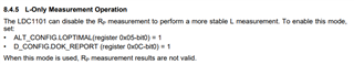
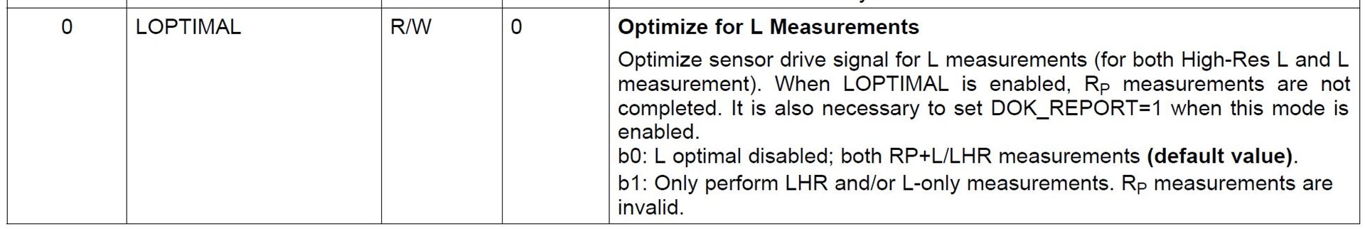
Section 8.4.5 of the datasheet mentions that the Rp can be disabled to improve measurement stability.  Can you please explain what a more stable measurement means and how it is measurable?

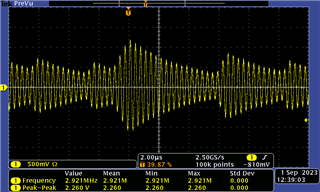
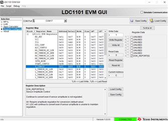
I would like to measure the effect of this change on the LDC1101 EVM.  Please let me know what kind of test setup I can use to demonstrate a difference when L-Only measurement is configured.

Thanks,

Arthur

  • Arthur,

    The measurement is more stable because with those settings, the device optimizes the current thru the sensor.
    This is described in the register listing on page 19 of the data sheet.

    You should be able to execute the measurements with our LDC1101EVM, which also has a supporting GUI.
    It should just be a matter of setting the fields as described in the data shhet.

    Regards,

    John

  • Hi John,

    Can the stability improvement be quantified in any way?  Is the device using a current drive strength that is somehow superior for accuracy?  Would that be a higher or lower current?

    If you plug in a LDC1101 EVM on your end, can you demonstrate any change in the behavior when you apply this setting?

    On my end I tried to take a waveform measurement on the LDC1101 EVM after applying this setting, and it did not match my expectation.  I saw the decaying waveform - that made me think the device might still be measuring Rp, despite my attempts to disable the Rp measurement.

  • Arthur,

    the questions so far cover a pretty broad area.

    If we narrow the topic, we will most likely get the answers you are looking for more quickly.

    First things first: What behavior and performance are you looking for?
    What are your end goals?

    Regards,
    John

  • 1.  Our application only uses LHR measurements, yet we have not disabled Rp measurements.  It would be nice to get improved sensing performance (metal proximity sensing) with only a software upgrade.  So far on the bench with the EVM, I have been unable to prove any sensing performance gains by changing the setting (such as standard deviation of the measurement with a static target present, for example).  What aspects of the performance are actually optimized when we "Optimize for L Measurements"?

    2.  I am curious whether the Register Configuration section of the LDC1101 EVM GUI actually works. - I am able to write my changes to ALT_CONFIG and D_CONFIG and read them back successfully. But when I click back to the LHR tab I suspect that the sensor is re-initializing to some baseline mode where Rp measurements are again enabled, ignoring the changes I tried to make.

  • Arthur,

    I will try to reproduce you findings with the GUI and will update this thread by COB on Thursday.

    Regards,
    John

  • Arthur,

    Could you share a few more details about what you are seeing w/respect to item #1?
    1.1 Are you using the EVM on-board sensor coil or an external one?
    1.2 What are you using for a target and what are its dimensions?
    1.3 What is the distance between the target and the sense coil in your measurement?
    1.4 Are there other metrics - in addition to the measurement standard deviation - that are important for your application?

    2. Could you share the register settings you mentioned in item #2?

    There are some app notes that may be helpful:

    1. Setting LDC1312/4, LDC1612/4, and LDC1101 Sensor Drive Configuration - the author provides guidance on amplitude settings and why automatic amplitude settings may not be best (sections 4 & 9).

    2. Sensor Design for Inductive Sensing Applications Using LDC - a must-read if you are new to inductive sensing.
    It talks about the practical aspects of layout, PCB parameters, parasitic capacitance, and their impact on a sensor design. Somewhere in there the author mentions the target-to-coil distance should be kept to 3% to 20% of the coil diameter for the best accuracy. Separation distances of up to 50% can be supported, but at reduced accuracy. 

    3. Configuring Inductive-to-Digital-Converters for Parallel Resistance (RP) Variation in L-C Tank Sensors - it doesn't explicitly address the LDC1101, but it gives a great overview of the Rp impact on inductive sensors.

    4. Optimizing L Measurement Resolution for the LDC161x and LDC1101 - it can be challenging to apply the contents of this paper to a design, but it does provide some insights on the factors that contribute to inductive position-sensing resolution.

    Much more info is available at the [FAQ] Inductive sensing FAQ - Frequently asked questions.

    regards,
    John

  • Hi John,

    1.1. on-board EVM sensor coil

    1.2. A steel disc 32mm in diameter, 1mm thick.

    1.3. 10mm

    1.4.  Fast measurement speed is important, as we prefer to save power by taking one ~1msec measurement every 1 second.  If the measurement takes longer, it increases power consumption.

    2.  The register settings are the same mentioned in the datasheet 9.1.11: 

    ALT_CONFIG.LOPTIMAL(register 0x05-bit0) = 1 

    D_CONFIG.DOK_REPORT (register 0x0C-bit0) = 1

    Your app note #1, Section 9, referred me to that section in the datasheet.

    So I am trying to ask about that #1 app note you linked, should I follow its advice and disable the automatic amplitude control?

  • Arthur,

    Disabling automatic amplitude control is the most reliable way to go since the automatic adjustments are out of your control and your goal is high precision/resolution.
    This approach may require you to manually adjust the IDRIVE setting over the range of the target movement, but that will be dictated by your application and requirements. It will take some experimentation and trial and error.

    Two more resources that may be helpful:

    1.  The LDCCOILEVM may have a coil that is close to the sensor on the EVM. Try cross-referencing & comparing the EVM's coil description given in the  LDC1101 EVM User's Guide to one in the LDCCOILEVM User's guide which should show inductance and Rp measurements versus frequency for that coil. That may help provide a starting point for IDRIVE settings.
    2.  Enter the EVM's coil description given in the  LDC1101 EVM User's Guide into the Inductive Sensing Design Calculator Tool on the Spiral_Inductor_Designer tab and enter the results in the LDC1101_calcs tab. It will give feedback on proposed device settings as a starting point.

    Regards,
    John

  • Hi John, thank you for sharing the additional design resources.

    My question from above in the thread:

     I am curious whether the Register Configuration section of the LDC1101 EVM GUI actually works. - I am able to write my changes to ALT_CONFIG and D_CONFIG and read them back successfully. But when I click back to the LHR tab I suspect that the sensor is re-initializing to some baseline mode where Rp measurements are again enabled, ignoring the changes I tried to make.

    You replied that you would try to reproduce my findings with the GUI - did you find an answer?

  • Arthur,

    I was able to reproduce what you have seen with the Registers page.
    The steps are below.

    1. Set the ALT_CONFIG and D_CONFIG LSB bits to b1 per section 9.1.11 of he data sheet,
    and save the configuration.

    2. Go to the Apps calculator panel, and then return to the Register Configuration panel and the register edits were unchanged:

    3. Transition to the LHR panel and back, and the registers' LSBs have returned to b0.

    4. Load the saved Config saved in item (1) and the bits are back to b1.

    5. Transitioned to  the LHR panel, selected Load Config, and the GUI lost its COM port connection.

    6. After a few rounds of Load Config, losing and then re-establishing the connection on the LHR panel,
    I was able transition back to the Register Configuration panel with the LSBs still at b1 in the Register Map display..
    But.... even though the Register Map display shows the two LSBs at b1, the corresponding Register Data
    check-boxes are unchecked. Not sure what this means.
        

    7. Re-doing Load Config yet again on the Register Configuration page results in the checks showing up in the boxes.
        

    So in summary, its not clear exactly what is happening.
    It looks like there's some kind of conflict in the GUI S/W.

    Regards,
    John

  • John,

    Thank you!  It's good to know it's not just me having the problem.

    I am afraid it may not be realistic for me to expect updates to this old application.  Is there anyone supporting the app who can let us both know if there's a workaround for this issue?

    Thanks again,

    Arthur

  • Arthur,

    As you said, this is an old application, and to my knowledge there are no work-arounds for this issue.
    I tried for several hours to find one, with no luck.

    John

  • John,

    I should be able to write a script to manually perform register reads/writes over the COM port.  I assume even if the GUI is buggy, I can change the settings that way.

    If I'm able to make the change, would I see a difference on the voltage waveform I'd previously measured?  Should the amplitude remain constant instead of decaying like this?  I can't find anywhere where it's clearly spelled out what is supposed to be happening.

    Thanks,

    Arthur

  • Arthur,

    You are completely correct.  The shape of the waveform is not clear from the documentation.
    Some experimentation wit the GUI and EVM resulted in a constant amplitude  for LHR mode by setting RPmin and RPmax to the same value.

    I have no idea what this does for the accuracy, but it does get rid of the varying envelope of the sensor waveform.
    The amplitude could be varied by adjusting the RPmin = RPmax values to other thee-bit combinations.
    Note the data sheet cautions against settings which give RPmin > Rpmax.

    Regads,
    John

  • Hi John, I am concerned if I set my device to have RPmin = RPmax, it wouldn't be stable over all target distances.  I will not always have the target present at 10mm distance, sometimes the target will be missing.  So the LDC1101 may fail to start the oscillation in some cases and be unable to provide a measurement.

    I still want to try the serial port method of setting the ALT_CONFIG and D_CONFIG LSB to 1, and I'll let you know if that works.

  • Steps below to try the disable Rp setting:

    Follow the 3.15 EVM FW Protocol in the EVM Users guide https://www.ti.com/lit/ug/snou137/snou137.pdf
    Use Coolterm to send serial strings:

    020B01 - stop conversions, Start Config. the Scope waveform disappears
    020501 - write register 0x05 to 1
    020C01 - write register 0x0C to 1
    020B00 - write register 0x0B to 0. This is START_CONFIG, when set to 0 it should start active conversions

    The scope waveform now has a constant amplitude. The constant amplitude is too high. Per https://www.ti.com/lit/an/snoa950/snoa950.pdf, it should be between 1.0 and 1.25V peak (2 to 2.5V P-P).
    tek00121.png

    020B01 - stop conversions, Start Config
    020105 - Try setting RPMIN to 0x04, 3k ohms.
    020B00 - oscilloscope waveform appears. Peak-Peak is ~1.

    tek00123.png

    now close coolterm and launch ldc1101EVM GUI. The sensor gets reconfigured as soon as I launch the program without clicking any other buttons. So it won’t be possible to use the EVM GUI to gather measurements with these Rp disabled settings.
    tek00125.png

  • Arthur,

    Thank you for the update.

    Regards,
    John

  • Arthur,

    With regards to a ferrite shield, one of my colleagues tested an LDC1614 and an LDC3114 with ferrite shield.

    Subjecting the ferrite to a fixed magnet made no observable difference in the behavior or performance of either device.

    Regards,
    John