This thread has been locked.

If you have a related question, please click the "Ask a related question" button in the top right corner. The newly created question will be automatically linked to this question.

DRV5013-Q1: VDD Reverse Polarity Protection

Part Number: DRV5013-Q1
Other Parts Discussed in Thread: DRV5013

Hi,

A customer asked us about how to provide Reverse Polarity Protection for power supplies.
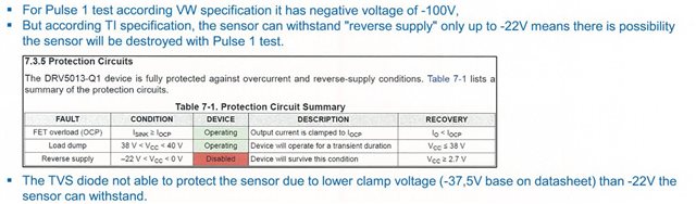
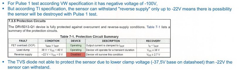
Applying a reverse polarity voltage (-100V) to the power supply terminals is not recommended usage, can TI advise customers on how to do this?

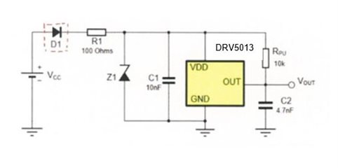
The circuit they are considering is simply a diode connection to VDD.

This test content is a Volkswagen test item, so countermeasures are required, and if TI has any knowledge, please let us know how to countermeasures.

In addition, the customer is considering the following products.
Vishay : ESD1DHE3_A/H
GSD2004W-HE3-08
Onsemi : NRVA4004T3G


Best regards,
Hiroshi

  • Hey Hiroshi,

    This document looks like it might be helpful.  That zener diode looks like it would keep the potential between device ground and device Vdd to something smaller -20V, which seems promising. Also those diodes look like they are rated for at least 100V repetitive peak reverse voltage, which suggest that those should survive from a voltage standpoint.  The reverse current looks like it is 1mA worst case, depending on the diode chosen, which is well beneath the abs max for output pin reverse current for the DRV5013.  I will see if our design team has any comments for current at the supply pin.  

    Can you comment on where this -100V comes from?  If your customer really has a 100V supply that is reversed, then I do see a possible issue for when that supply is not reversed.  If you have  a +100V vcc then you will likely be sinking alot of current through z1 or you may potentially have the DRV5013 at a voltage above the abs max.  If the -100V is from some sort of inductive kickback, then it might make sense to place the diode somewhere else.

  • Hi Patrick,

    Thank you for your support.

    The test method for -100V negative voltage input is based on VW's required specifications.
    It is not an inductive load. The test method is below. 


    VW TL81000 2021-09

    Here are some excerpts from customer reports.

    Considering that this is a request from a major automaker, I thought that TI might already have a countermeasure in place, so I contacted them.

    Best regards,
    Hiroshi

  • Hey Hiroshi,

    We dont have a reference design specific to our hall sensors with reverse protection.  However, TI does have some documents on reverse current or reverse voltage protection.

  • Hi Patrick,

    Thank you for answering.
    I'm currently waiting for your response, but I'll mark this thread as resolved.

  • Hello Hiroshi,

    I spoke with our design team, they would not provide me a reverse current max value for the supply.  They reiterated that the max reverse voltage is -22V and they said if you managed to current the limit the reverse voltage, the device would likely see less than -22V.   As for the best protection diode, I suggest you reach out to one of the diode manufacturer's for the diodes you listed above.

  • My previous reply was wrong.
    I will answer based on your answer and wait for the customer's response.

    Thank you very much for your detailed explanation.