


Hi TI experts
A PCB prototype was designed using the IWR6843AOP chip.
There is an issue with downloading here, so please leave an inquiry.
I designed SOP 0 - 2 as shown in the circuit below. Are there any parts that could be an issue?
SOP0 is designed with a 3.3v pull-up of 10k.
SOP1 was designed with a pull-down of 10k.
SOP2 was designed as a combination of 10k, 82.5k, and 7.87k.
I designed it based on the EVM board, so please check it again.
The part that I think will be the issue is SOP 0.
On the EVM board, SOP0 is a combination pull-up of 10k and 7.87k.
Only 10k was installed on my PCB.
Could this cause problems with downloading?
Request you to check.
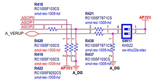
P.S ASOP0 is connected to pin U10, ASOP1 is connected to pin M3, and ASOP2 is connected to pin V10.
Best regards,
Dave
