This thread has been locked.

If you have a related question, please click the "Ask a related question" button in the top right corner. The newly created question will be automatically linked to this question.

LDC1101: Stainless steel target

Part Number: LDC1101

Hello,

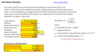
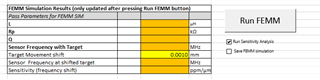
I need to use the LDC1101 to sense the distance to a target.  The LDC1101 will be 1 mm away from the target and the target can move 3 mm away from the sensor.  I have tested the same setup with an aluminum target and the results are good.  Now I need to change the target material from aluminum to 17-4 stainless steel.  Are there any considerations that I need to take into account given the higher resistivity of stainless steel as compared to aluminum or should I expect similar results?  I would like to avoid any pitfalls ahead of time.

Thanks,

Narek

  • Hello Narek,

    Yes, you do need to take the resistivity into consideration as this will have an effect on the skin depth.  Section 2.2 of the app note below discusses this.  It is recommended for target thickness of 2 to 3 skin depths.  

    https://www.ti.com/lit/an/snoa957b/snoa957b.pdf   

    You can also use the LDC calculator tool to estimate the skin depth for a given material, thickness, and frequency.  You may find that your target thickness or frequency needs to be adjusted for the new material. 

    https://www.ti.com/tool/download/LDC-CALCULATOR-TOOLS 

  • Hi Eddie,

    Thanks for the response.  I had already taken a look at the required skin depth and looks like I'm OK there.  The target is 2 mm thick, so we're looking at about 5 skin depths.

    There were some radical changes, though, in some of the parameters when the resistivity was changed from 1.68e-8 (copper) to 8e-7 (17-4 SS).  I've attached screenshots of the spiral inductor design calculator.  The left-most is the original design used for the aluminum target.  The middle shows the changes that result strictly by changing the resistivity.  The table on the right shows the results when the capacitance was radically reduced.  I'm using the sensor in LHR mode only.

    The operating frequency has increased dramatically and the Q is still too low.  Do you have any recommendations?

    Thanks,

    Narek

  • Narek,

    The resistivity parameters you are changing are for the coil and not the target material.  If you are still using a copper PCB for the coil, you should not change these parameters.

  • Hi Eddie,

    Thank for pointing that out.  Clearly, I did not read where it says "conductor resistivity" right next to it!

    I have a few follow up questions.

    1. So long as the target thickness allows for greater than, say 3 skin depths and the frequency is set to a reasonable range, the material of the metal does not matter.  Is this correct?

    2. I was playing around the the sensor's operating frequency by adjusting the sensor capacitor value and noticed that the difference in frequency between "no target" and "with target" (when the target is at its closest) increases as the capacitor value is decreased.  For example, for the specific coil that I have designed and with 470 pF as the capacitance, the difference in frequency is 1.744 MHz - 1.272 MHz = 0.472 MHz.  If I set the capacitance to 220 pF then the difference is 2.537 MHz - 1.851 MHz = 0.686 MHz.  So the sensitivity or dynamic range increases.  Also the skin depths increase due to the increases in frequency.  All of this seems like the right thing to do, but I would like to know if there is a downside to lowering the capacitance, but not so much where Rp and the sensor frequency go out of range?

    Thanks,

    Narek

  • Hi Eddie,

    I forgot to ask one more question.

    3. If the target is aluminum but type-II anodized, would the anodization be an issue?

    Thanks,

    Narek

  • Narek,

    1. The performance may not be identical since the aluminum still does have a better resistivity characteristic.  The aluminum target will still achieve a better range.

    2. Your observation is correct that dynamic range will increase using a higher resonant frequency.  There is an effect of the Q factor lowering when changing the capacitance, so you dont want to get too carried away, but typically this is more of a problem when there is too much capacitance and this creates too high of a Q.  Another reason you may want to select a lower frequency could be due to the environment that you will operate in may be susceptible to certain frequencies. 

    You can also use the FEMM version of the calculator tool, which can simulate different metal types at a specific range.  When using this, be sure to check "run sensitivity analysis".  This will allow you to input a target movement shift, then click "Run FEMM".  It will take a few minutes to run the simulation, but the results will include the shifted sensor frequency.  You can run some different configurations and see what kind of sensitivity is possible.  The FEMM simulation will also provide a better accuracy than the excel calculations, although take much longer(simulation vs. calculation).   

    https://www.ti.com/tool/download/LDC-CALCULATOR-TOOLS 

    3. I think the anodization will have a minimal effect.  The eddy current can still move along the skin of the conductor and the anodization should not effect that.  The anodization will add a bit of thickness to the target, but I think this is negligible.

    Hope this helps!  It looks like you are moving along the right path.  Let me know if other questions come up or feel free to start a new thread.

  • Hi Eddie,

    Thank you for the answers and your suggestion to use FEMM.  I ran a simulation based on the same parameters that I had used for the calculated version.  I have a couple of questions.

    1. The sensor frequency for target interaction is calculated as 2.537 MHz.  The FEMM Excel spreadsheet provides the warning "Fsensor is too low", but the calculator spreadsheet does not, even though the value is the same for both.  Any idea why this is and is this frequency considered too low?  I have already prototyped the same coil with an even lower frequency using the calculator and it did not complain there either.

    2. The FEMM results are in the ballpark compared to the calculated values for the upper and lower frequency values.  I'm not quite sure how the sensitivity value (ppm/µm) is determined, though.  Would the sensitivity be the difference in the upper and lower frequencies divided by the shift value of the target?

    Thanks,

    Narek

  • Hi Narek,

    1. Be sure that you have the correct device selected in cell D20.  If you still see the error, please send your full configuration.  I did not see the error myself with configuration down to ~500kHz.    

    2. Yes, the sensitivity is probably better expressed as MHz/µm instead of ppm.  This is (f1 - f2) / distance.

    If you are interested in the resolution, there is also detailed information in the app note below.  Section 4 discusses calculating this using an EVM to get a reasonable noise floor estimate.

    https://www.ti.com/lit/an/snoaa04a/snoaa04a.pdf   

  • Hi Eddie,

    Yes, the incorrect device was selected, although I was sure I had chosen the LDC1101.  In any case, thank you very much for your help!  It is greatly appreciated.

    Narek