This thread has been locked.

If you have a related question, please click the "Ask a related question" button in the top right corner. The newly created question will be automatically linked to this question.

TMCS1100: Current measurement of lower IGBTs in a three phase half bridge configuration.

Part Number: TMCS1100
Other Parts Discussed in Thread: TMCS1123

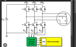
I want to use TMCS1100 as a shunt to measure currents of lower leg of IGBT. See the below figure. In this I want to replace Ra Rb and Rc using TMCS1100.  Since the switching freq is around 6-7khz, BW is not much of a problem. The thing i am concerned about is that,  can I use this to measure the current if the DC link voltage is 800V. Since any one IGBT will be blocking the DC voltage ( maximum) is it safe to operate ??

  • Hi Archit,

    Thanks for the question and using the E2E forum.

    Unfortunately in this case the TMCS1100 isn't suitable as it's only capable of handling up to 600V.

    However, our newer TMCS1123 has a much higher isolation voltage that might work better for you.

    Pleas let us know if you have any other question.

    Louis

  • Thanks for the suggestion @Louis . However my question was different. Since I will be connecting between the lower IGBT Emitter and DC negative, The IGBT should block the maximum voltage and the sensor IC will never see the full DC link. Am I missing something here?

  • However, our newer TMCS1123 has a much higher isolation voltage that might work better for you.

    Also, can I use this TMCS1123 to measure the IGBT current instead of Motor Inline (phase) currents?

  • Archit,

    I'm in agreement, I don't see any issues with your initial arrangement, provided you don't have any shoot through conditions that might potentially expose the device to the full DC link (I'm assuming the TMCS1123 is the same ground as the DC link? Cannot see how the device is terminated in the photo above). That being said, what is the average current you are planning to pass with the system? I'm assuming it wont be much given the DC link is 800V, but it bears asking, as the TMCS1100 is only capable up to 15A continuous provided there is sufficient copper to handle the thermal issues. The next gen TMCS1123 Louis mentions above provides several improvements to the original design, including ambient field rejection, built in diagnostics, and much lower internal resistance for better thermal performance. It is however larger to handle the additional current potential. 

    The answer to your second question is yes. The device provides reinforced isolation at 1.1kV, so you certainly could measure on the high side with the TMCS1123. 

  • Thanks a lot Carolus for the confirmation. The current will be around 10 Amps rms.