This thread has been locked.

If you have a related question, please click the "Ask a related question" button in the top right corner. The newly created question will be automatically linked to this question.

LDC1612: Regular Oscillations in Output Codes Over Linear Displacement

Part Number: LDC1612
Other Parts Discussed in Thread: LDCCOILEVM,

Hello,

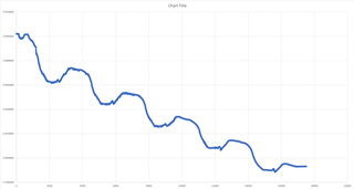
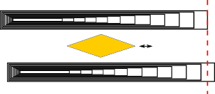
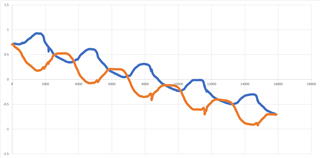
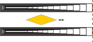
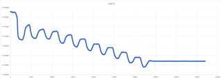
I am seeing some unexpected output code oscillations which trend in the expected linear direction over any linear displacement. The oscillations appear to repeat every 2mm. The following data was taken with Test Setup #1 as described below. For this test, a 4mm wide copper target was roughly 1-2mm away, and moved 20mm over the coil. The coil used was Coil B from the LDCCOILEVM sample kit. Note: The steady reading towards the end was when the target stopped moving (hit the 20mm mark), but the EVM GUI was still recording.

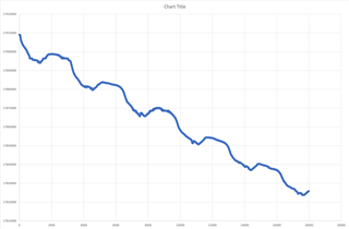
The following was taken using the same setup (Test Setup #1), except a 15mm target over 11mm travel distance over the coil.

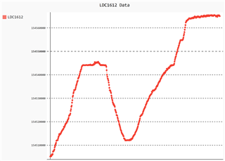
Below is a sample output from Test Setup #2 (custom PCB, described below), using a 4mm wide copper target over a linear displacement of just a few mm, on a custom PCB & coil. Opposite direction as the two examples given above.
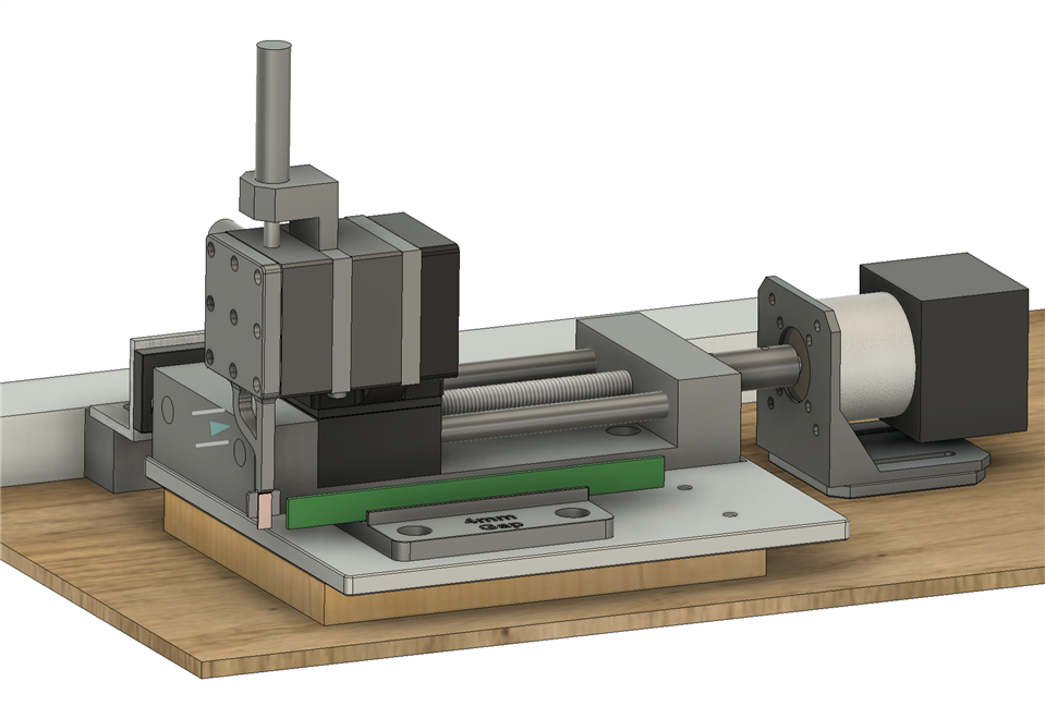
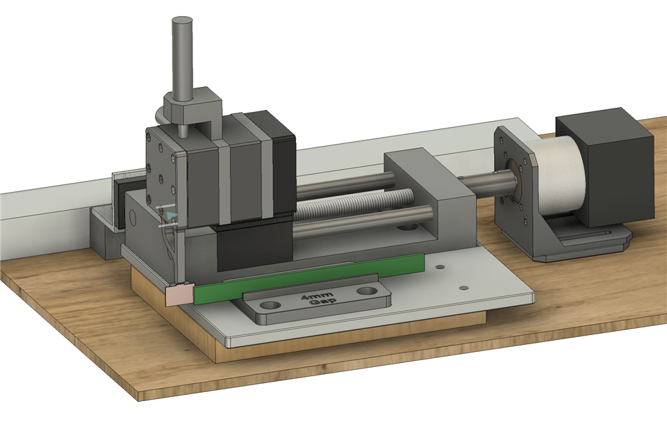
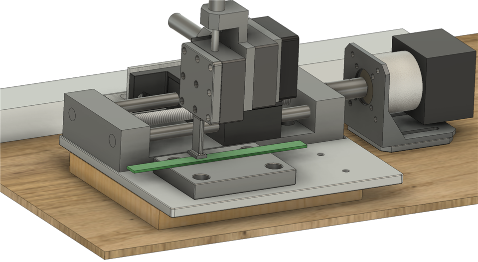
Test Setups:

The results have been replicated in the following two fairly different test setups:

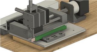
  1. Using the 1614 EVM with Coil B or C from the LDCCOILEVM sample kit on a reduction geared stepper motor test fixture with position feedback (5um resolution). The motor drives a rail guided linear stage to accomplish the linear displacement. Tested with both a 4mm wide and 15mm wide copper target extending beyond both ends of the coil at 1-2mm distance from the coil.
  2. Using a custom PCB with a LDC1612 and a built-in rectangular coil (80mm x 8mm). Using the same stepper motor fixture as test setup #1. Tested with a 4mm wide copper target extending beyond both ends of the coil. 1-2mm distance from the coil.

Do you have any suggestions for removing the oscillations from the output, or possible causes for this issue?

Please let me know if you need any additional information about my test setup or configurations.

Thanks in advance for any recommendations or support.

Best,

Minnow

  • Minnow,

    Do your requirements allow you to use targets with a larger area?

    Regards,
    John

  • Hi John,

    Thanks for your reply.

    A smaller target is strongly preferred.  Even with the 15mm target I am seeing the oscillations. That is almost 2x the coil width.

    Are these oscillations expected behavior with a smaller target? What is the recommended ratio to avoid these oscillations?

    Best,

    Minnow

  • Minnow,

    It would be good to clarify the position and movement of the target over one of your coils.
    Can you provide a diagram?

    Are your targets always square or rectangular?

    Regards,
    John

  • Hi John,

    The coil fixtures are set up as below. Absolute position along the sensor was not recorded, however, we are not using ~15-20% on each end in order to avoid the less linear portions. The targets are rectangular, but on fixture 1, the 15mm target has a narrow portion of copper protruding from the top, so it looks like an upside-down 'T'. The fixtures directly in contact with the target and the coil PCB are both plastic, as is the base plate under them. The assembly is installed on a wood slab.

    Fixture 1 - 4mm target over TI Coil B. The target is shown as driven past the end of the coil for this explanation, however measurements were taken towards the center of the coil. There is a deep slot on the far side of the coil to allow the target to extend beyond the width of the coil. The same is true for the 15mm target.

    Fixture 1 - 15mm target over TI Coil B:

    Fixture 2 - TI Coil B shown, actually custom PCB with 8mm x 80mm coil: There is a 4mm wide copper target attached to the bottom side of the moving fixture (not visible due to the angle).

    I hope this clarifies the test setup.

    Best,

    Minnow

  • Minnow,

    thank you for the diagrams. They made things much clearer.

    I think you may be seeing the impact of the target's edges moving between the coil's windings.
    As the target's edge moves past one winding and moves along to the next one, it will be over the equivalent of empty space.

    Please try using a different target shape, other than a square or rectangle.
    A diamond or rombus may be a good start. The idea is to make the leading and trailing edges of the target have not so abrupt declining/increasing overlap of the coil's winding. That may smooth things out.

    regards,
    John

  • Hi John,

    Thanks for the suggestion. I gave it a try, but unfortunately it did not seem to fix the issue. Below is the target shape I used, followed by the output over 10mm displacement. The target height is 10mm.

    Have you seen similar oscillations? Some of the TI documentation has graphs created from measurements taken every 0.5mm - for example this blog post. I'm curious to know if you zoom in on that data you will see similar oscillations.

    Best,

    Minnow

  • Minnow,

    Unfortunately the data from that blog is no longer available.

    It looks like the ripple component magnitude (vertical scale) is about ±10k, which for your overall magnitude is about 550ppm.
    The period of the ripple looks to be about 3000 (horizontal axis).

    If the  horizontal axis (0 - 18000) in the latest plot represents the entire 10mm displacement , then the ripple appears to create a positional uncertainty of about 10mm x (±1500/18000) = ±0.83mm. 
    Does this agree with your findings?

    If we can't completely eliminate the ripple, can we use this type of calculation to determine the level of ripple that would be acceptable?

    Regards,
    john

  • Hi John,

    Thanks for following up.

    Regarding your question as to what level of ripple would be acceptable: I was looking for positional uncertainty at least more than an order of magnitude better than the +/- 0.83mm. If there are additional mitigation strategies you can suggest to reduce the ripple, please let me know- I would be happy to give them a try.

    One other possibility is that the linear X stage in my fixture has slightly misaligned lead screw bearings, causing repeated changes in target distance from the sensor coil. I ran two tests to explore this. Both tests have two sensor coils parallel to each other, on edge, with the target moving down between them:

    The two tests were the following:

    1) Two coils parallel to each other, but offset the coils. Standardized output shown.

    2) Two coils parallel to each other, as close to matching alignment as possible. The output here was essentially the same as the offset coils.

    The thinking was that if the issue is coil & target dependent, I would see the ripple offset on the X axis, along with the coil. However, it seems that the ripple is always in phase between the coils, regardless of offset. The ripple of one coil is also the inverse of the other coil, which further suggests mechanical target height changes could be at play. I'll need to set up a fixture to decouple any movement from the X-stage that is not on the X direction.

    Thank you for your support and suggestions,

    Minnow

  • Minnow,

    Would it be possible for you to use multiple coils placed end-to-end?
    If that would be okay, you might be able to use coils with uniformly spaced windings and track the position of the target as it moves across the different coils.

    Regards,
    John