


Hi Team,
The customer would like to use a PCB coil as the LDC1612 sensor to measure the distance of the PCB coil to a silver-plated mirror.
Issue:
During the movement of the PCB coil (4 mm-20 mm), it is not possible to measure the entire distance with one drive current, or if only one drive current is used, the PCB is too close or too far away from the silver-plated mirrors with amplitude errors.
PCB parameters: PCB diameter up to 26mm due to size constraints (all other parameters can be varied)
Measurement range (PCB coil approximately 4 mm from silver plating due to mirror and assembly): 4 mm-20 mm.
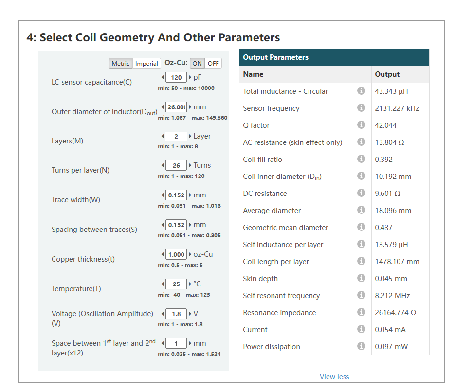
The PCB coil parameters currently designed are as follows:
At the same time, to limit the orientation of the PCB magnetic field, a round ferrite is placed on the back of the PCB coil, but it also results in a reduction in the overall resonant frequency.
1) Can the coil be redesigned such that the entire process uses only one drive current to complete the measurement?
2) If different drive currents are used throughout the measurement phase, it is obvious that the measurement results are not available, that is, the conversion results are jumping. Is there a way to solve this problem?
3) Would it be possible to disregard the amplitude error that occurs? However, experiments have shown that when amplitude errors occur, a bad result can be apparent.
Could you help check this case? Thanks.
Best Regards,
Cherry
