This thread has been locked.
If you have a related question, please click the "Ask a related question" button in the top right corner. The newly created question will be automatically linked to this question.
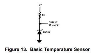
I want to know the output voltage in the circuit of FIG.
Looking at other threads of LM35, it was written that the output voltage can be expressed by the following equation.
Vout = 10mV/C + 2 × Vd
Vd is the voltage applied to the diode
When I saw this, I was convinced at first.
But when I thought about the voltage applied to the diode, I felt that it might not be constant.
The voltage across the diode seems to be affected by temperature and current.
I would like to know what the final Vout will be in this situation.
Where should I look at the datasheet and think about it?
There was also a thread recommending TMP235, but is that better?
I want to measure from -20°C upwards
In this drawing, Vout must be measured differentially. You could use a multimeter or differential ADC. You could not use a single-ended ADC or an oscilloscope. The voltage of the 1N914 would be summed with the LM35 output in the latter scenario, because single-ended measurements are referenced to GND.
LM35 was released in 1983 when negative voltage power supplies were more commonly available in circuit designs. Today, negative voltages are very rare, and circuits like Figure 18 are needed to adapt the old LM35 to a single positive supply voltage. This is because LM35 outputs 0V at 0C.
TMP235 is a modern LM35 replacement that has a built-in voltage offset to allow it to report negative temperatures without going below 0V output. TMP235 outputs 500mV at 0C.
I recommend that you use TMP235 in your design instead of LM35. We also have a variety of other analog output temperature sensors available with different V/C gain. https://www.ti.com/sensors/temperature-sensors/analog/overview.html
thanks,
ren
Thanks for the reply. Your answers are very helpful.
I'm going to try using the TMP235. I wonder how to decide on R1 ...?