This thread has been locked.

If you have a related question, please click the "Ask a related question" button in the top right corner. The newly created question will be automatically linked to this question.

OPT3101-SDK:Questions about calibration SDK step INLAB_STEP_1

Part Number: OPT3101-SDK
Other Parts Discussed in Thread: OPT3101

I have performed the calibration step INLAB_STEP_1 -> dev.calibrationSession_firstTimeBringUp();
As far as I know, this step performs the calibration.
* Internal electrical crosstalk
* Offset Illumination crosstalk
*Phase Offset

I have managed to carry out this step. I have significant mm distance measurements. There is still a percentage of error, but I think it is due to my calibration tools.

Regarding my results I have some questions:

1- Should the same OPT3101 configuration be used to calibrate as for field operation mode. For example, if I calibrate with an OPT3101 configuration in AutoHDR mode as it comes in the SDK (OPT3101_configuration.cpp), in my application I configure OPT3101 in SuperHDR or monoshot mode as long as I load the records with the calibration values, will the behavior be the same?

2- Does this calibration constitute the factory calibration that must be carried out for each OPT3101 PCB, what are the consequences of not doing it for each unit, that is, using the same calibration values for my entire production batch?

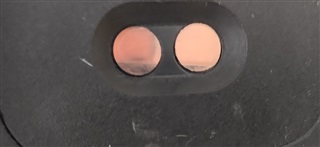
3- My OPT3101 PCB design will be inside a case covered as shown in the image and with a coverglass, my question here is should this calibration be carried out with the PCB module mounted in the case or is it better to have the PCB discovered online production ?

  • Hi Guillermo,

    Our OPT3101 expert will get back with you soon.

    Jalen


  • Guillermo,

    It's better to turn HDR off and force the device to each intended tx current for each step. HDR or AutoHDR will cause errors as it is automatically changing the levels. You do not want this. This could be part of the distance errors you see.

    You have probably read the https://www.ti.com/lit/pdf/slau791 -  How to set up and calibrate OPT3101 based systems for proximity sensing. If not please do so. 

    The most important parts of the calibration is to correct for noise also know as electrical and optical crosstalk. If you place the PCB into an enclosure after the calibration you could be introducing reflected electrical or optical after the calibration. It would be best to calibrate your board after it is placed in the final packaging if at all  possible to get the greatest benefit form the calibration. Remember even flat glass can reflect a small amount of light going out and coming in. You will want to correct for that.

    This would be considered the factory calibration. Then upon start up you can perform the internal electrical crosstalk calibration with each startup. This would not require involvement from the user just a few extra seconds and it will maximize the system accuracy.  

    Let me know if you have any other questions. 

  • Hi Gordon.
    Thank you for your comments.
    Just one more question, you mention that the calibration must be carried out with the Super-HDR or Auto-HDR mode off. Could you explain a little more about what this process would be like because if a configuration like this is made:

    void OPT3101::device::initialize(void){
    	// List of registers to initialize OPT3101 device after power-up
    
    	this->reg.force_en_slave = 1; // //Since I2C Master bus is floating this register needs to be set to enable device to respond
    
    	this->reg.tg_ovl_window_start = 7000; // //Overload flab observation window
    	this->reg.en_temp_conv = 1; // //Enables the internal
    
    	this->reg.clip_mode_fc = 1; // //Enables Clip mode for Frequency correction
    	this->reg.clip_mode_temp = 0; // //Disables Clip mode for Temp coff phase correction
    	this->reg.clip_mode_offset = 0; // //Disables Clip mode for phase offset correction
    	this->reg.iq_read_data_sel = 3; // //Enables 16 bit frame counter
    	this->reg.iamb_max_sel = 0; // //Sets maximum ambient support
    	this->reg.en_temp_corr = 1; // //Enables Temperature Correction
    	this->reg.gpio1_obuf_en=1; // //Enabled output buffer on GPIO1 pin
    	this->reg.gpo1_mux_sel=2; 	    // //select dig_gpo_0 on gpio1
    	this->reg.dig_gpo_sel0 = 9; 	// //Select Data Ready on dig_gpo_0
    
    	this->reg.num_sub_frames = 127; // //Sub frames count
    	this->reg.num_avg_sub_frames = 127; // //Average frames count
    	this->reg.xtalk_filt_time_const = 3; // //Crosstalk filter time constant
    	this->reg.tg_seq_int_start 	= 9850; // //Sequence Start
    	this->reg.tg_seq_int_end 		= 9858; // //Sequence End
    	this->reg.tg_seq_int_mask_start 	= 127; // //Same as AvgFrame Count
    	this->reg.tg_seq_int_mask_end 	= 127; // //Same as AvgFrame Count
    
    	this->reg.illum_dac_h_tx0 = 31; // //High Current settings [173.6mA:5.6mA X 31]
    	this->reg.illum_scale_h_tx0 = 0; // //Illum scale for H [173.6mA:5.6mA X 31]
    
    	this->reg.sel_hdr_mode = 1; // //Selecting H Channel by default
    
    	this->reg.tx_seq_reg   = 2184; // //Setting TX Switching order
    	this->reg.en_tx_switch = 1 ; // //Enable TX Switching order
    
    	this->reg.tg_en = 1; // //Enables Timing Generator
    
    	this->configurationFlags_xtalkFilterTau =  3; // //This is not a register but a settings flag for the SDK
    	this->configurationFlags_monoshotMode =  false; // //This is not a register but a settings flag for the SDK
    	this->configurationFlags_xtalkSettlingOneTauInMilliSeconds      =  256; // //This is not a register but a settings flag for the SDK
    	this->configurationFlags_xtalkSettlingOneTauInDataReadyCounts   =  8; // //This is not a register but a settings flag for the SDK
    	this->configurationFlags_frameTimeInMilliSeconds                =  32; // //This is not a register but a settings flag for the SDK
    	this->configurationFlags_avgFrameCountExponentOfTwo             =  7; // //This is not a register but a settings flag for the SDK
    
    }
    

    OPT3101 works on a single channel, for my test it was TX0 HDR1, obviously I only calculated the lighting crosstolk for that channel, what about the rest of the channels?

    I would have to do the calibration for the TX0 HDR0 channel and save the calibration values, then the same process but now with the TX0 HDR1 channel and so on in general.

  • Hi Guillermo,

    Gordon will have to get back with you after the holiday

    Jalen

  • Guillermo,

    Turning off HDR for calibration was probably not the best description to use.  Take a look at the OPT3101Coefficients.cpp file of the SDK. To be honest the automated method using an MSP430 board and the SDK code is the best method of doing the calibration. Read the code, it will walk you through the entire process. 

  • Guillermo,

    A couple of more questions. Are you using more than one emitter? I assumed that you had one emitter and one photodiode (Receiver). You should be using TX0 if you only have one emitter. TX1 only if you are using more than one emitter. 

    The picture that you have presented shows two lenses. If one is the emitter and the other is the receiver, then you may have some optical crosstalk. If the emitter and receiver  can see each other in any way, then you will have a crosstalk issue. We typically have some kind of raised area between the two to prevent this. From your image you may need to place a raised edge between the emitter and receiver. Just thinking out loud. If you do have optical cross talk that would explain your issues.  

    Let me know what you are thinking. 

  • Hi Gordon.
    If I agree with you, following the SDK, the code guides you to do the calibration steps. Until now, I am at step INLAB_STEP_3.
    I was confused when you mentioned that HDR must be turned off, when the SDK has it activated in its default configuration file and that is how the calibration is performed, but I think you mean that it can change the current level automatically while I calibrate at a determined distance and this can cause errors in the measurements after calibration, you just have to set the distances before the HDR0.1 current level changes and set it to amplitude values 16000 to 24000 for each level of HDR0.1.

  • Guillermo,

    Yes I should have been more descriptive. There are times when HDR is on and off. The SDK guide will tell you what to do and when. The software will change the current based on distance and set HDR when needed. Follow the SDK Users Guide for best results. 

    In final use the HDR will change the gain based on amplitude and other factors to provide the best settings for the best accuracy and distance. The calibration will remove crosstalk, noise, and ambient based on gain for the distance. This will optimize your setup. 

  • It's clear now.
    About your questions
    * I only use one transmitter and one TX0 channel.
    * Regarding elevation, you mean placing a division between the sender and receiver. I use the same concept as the EVM, I have an Isolation ring and LED HOLDER on the emitter and receiver.