Other Parts Discussed in Thread: TMP61-Q1, TMP1075, , TMP1827, TMP61, TCA9544A, TMP107, TMP1826, SN74HCS125, BOOSTXL-TMP107
Hello E2E Community,
We are exploring different Analog & Digital Temperature sensors for our use case where we have to monitor the temperature of the machine components like Bearing Housing, Lubricating Oil temperature across pipe, Motor casing etc. So far we have planned to use TMP61-Q1 with 170'C range. However, we are now planning to explore a more integrated solution in the Digital Temperature Sensor portfolio.
- TMP1075
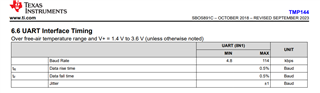
- TMP144
- TMP1827
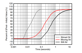
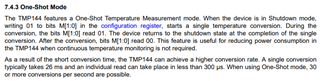
Among these shortlisted sensors, can you share with us what is the response rate to changes in temperature? The use case requires a temperature response rate of about 1 second at most, not more than this.
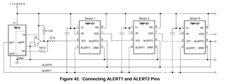
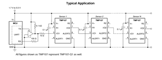
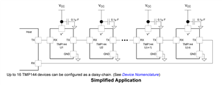
Further, we have to install these sensors at least 3m away from the MCU/ADC, we plan to use STP CAT6e cables for the sensor interfacing, can you suggest any suitable reference for any additional consideration to be implemented in such cases of longer cables?
Regards.