This thread has been locked.

If you have a related question, please click the "Ask a related question" button in the top right corner. The newly created question will be automatically linked to this question.

MMWCAS-RF-EVM: communication with another board

Part Number: MMWCAS-RF-EVM
Other Parts Discussed in Thread: AWR2243,

Hi,

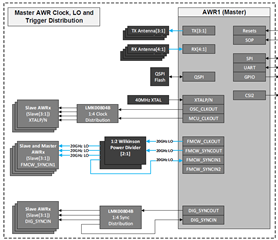
I'm trying to set up a connection between MMWCAS-RF-EVM (with 4 cascaded AWR2243) and another single-chip AWR2243 board. What I want to do is to use the cascaded board as a transmitter only and the single-chip board as a reciever only. Is it possible to do so? If yes, how can I setup the communication between these two boards and how to synchronize them?

Looking forward for your early rely, thanks!

  • Dear Yida - 

    Please see this application note which discusses cascading application, with connections and synchronization key points https://www.ti.com/lit/an/swra574b/swra574b.pdf , for you to use in your efforts. It may be very difficult to do what you describe without making a new PCB, as elaborated upon in section 2 of the document.  

  • Thank you for the quick reply! Yes I have seen this guidance before. My question is which physical port should I be connected to on both boards. For example, where should I attach a wire in order to get FMCW_CLKOUT from my cascaded board? Where should I check for the physical connection information?

    BTW, what is the relation ship between the already cascaded MMWCAS-RF_EVM and the cascade system in the above application note? Should the whole cascaded MMWCAS-RF_EVM be treated as the master or the master chip of MMWCAS-RF_EVM is the master of the system and other 4 chips (3 in MMWCAS-RF_EVM + 1 in the single-chip AWR2243) are all slaves?

  • Yida - 

    The design files are here : https://www.ti.com/lit/zip/tidm954 

    If you see the main page of the schematic, you will see the challenge that you face to adapt this hardware for your proposal as you would have to cut a line from the power divider for the LO, add one and re-route back to master, without changing the length, which means you would have to tune any coax you were going to connect almost perfectly, which may be practically almost impossible to do, as you will have to take the dielectric constant for whatever line you use and literally cut it down/trim it until you got it correct. You would also need to redesign the SYNC and clock distributions as well.  

  • Thank you for your reply. So if i use two single-chip boards instead of a cascade board and a single-chip board, is it more promising to achieve the transmitter-reciever system? Could you give me some advice or examples on the designing of the external PCB for rounting the synchronization signals?

  • Yida - 

    You will have to make that determination, choice and design. 

    There are full reference designs for two and four IC cascade available for you to use in/for your own development needs. These are there to support creative new developments as you have indicated you are interested in doing for yourself. 

    https://www.ti.com/tool/TIDEP-01012 

    https://www.ti.com/tool/TIDA-020047