This thread has been locked.

If you have a related question, please click the "Ask a related question" button in the top right corner. The newly created question will be automatically linked to this question.

TMP126-Q1: Unable to read temperature. Device ID reads correctly

Part Number: TMP126-Q1
Other Parts Discussed in Thread: TMP126

I have been trying to read from a PIC24 running SPI at 31Khz

Sending a 0x01, 0x0C, 0x00, 0x00 to get Device ID returns 0x21 0x26 as expected.

Sending 0x01, 0x00, 0xFF, 0xFF or any other value in bytes 2 & 3 just returns the byte sent  instead of the expected temperature read.

My configuration is written as 0x00, 0x03, 0x00, 0x84 - Average samples, Continuous,  250ms interval

Please help as 6 hours have been lost on this

  uint8_t receive_buffer[6] = {0};
    uint8_t spi_write_buffer[4] = {0x01, 0x00, 0xFE, 0xFE};


//    uint8_t spi_write_buffer[6];
 
    //-- Set bit-0 - Read command.
    // set chip select low to start comms
    SS_TEMP_SetLow();

    receive_buffer[0] = SPI1_Exchange8bit(spi_write_buffer[0]); // read  
    receive_buffer[1] = SPI1_Exchange8bit(spi_write_buffer[1]); // sub address
    
    UART2_Write(0xFF);
    
    receive_buffer[2] = SPI1_Exchange8bit(spi_write_buffer[2]); // Receive
    receive_buffer[3] = SPI1_Exchange8bit(spi_write_buffer[3]); // Receive

    SS_TEMP_SetHigh();


    UART2_Write(receive_buffer[0]);
    UART2_Write(receive_buffer[1]);
    UART2_Write(receive_buffer[2]);
    UART2_Write(receive_buffer[3]);

  • Further clarification based on questions in other posts.

    Initially the SPI was mode 0 but the clock was giving a ramped waveform like a capacitor was charging over several clock pulses. Changing to mode 3 corrected this and resulted in the Device ID returning 0x2126 as expected.

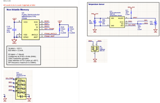
  • Can you share your schematic? I would expect that it's necessary to send 0x1, 0xC, 0xFF, 0xFF to receive Device ID. Have you looked at your logic levels for the Device ID transaction using an oscilloscope?

    thanks,

    ren

  • Sending a 0x01, 0x0C, 0x00, 0x00 to get Device ID returns 0x21 0x26 as expected.

    The above shows the TMP126 at 5v but we have changed this to 3.3v

    Here is the full listing for Initialise then read

    void temp_spi_initialise() {
    #ifdef TEMPERATURE_TEST

        uint8_t receive_buffer[6] = {0};

        // bits 0..7 sub address
        // set R/W bit 8 to 15 (write)

        uint8_t spi_write_buffer[6];


        // read chip serial ID
    // should return 0x2126 as the device ID
        //-- Set bit-0 - Read command.
        spi_write_buffer[0] = 0x01; // set R/W bit 8 to 15 (READ)
        spi_write_buffer[1] = 0x0C; // Read serial - bits 0..7 sub address
        spi_write_buffer[2] = 0x00; // NULL
        spi_write_buffer[3] = 0x00; // NULL

        // set chip select low to start comms
        SS_TEMP_SetLow();

        receive_buffer[0] = SPI1_Exchange8bit(spi_write_buffer[0]);
        receive_buffer[1] = SPI1_Exchange8bit(spi_write_buffer[1]);
        receive_buffer[2] = SPI1_Exchange8bit(spi_write_buffer[2]);
        receive_buffer[3] = SPI1_Exchange8bit(spi_write_buffer[3]);

        SS_TEMP_SetHigh();


        //    UART2_Write(receive_buffer[0]);
        //    UART2_Write(receive_buffer[1]);
        UART2_Write(receive_buffer[2]);
        UART2_Write(receive_buffer[3]);


        // configuration setup for temperature

        // 0000 00x1 0000 0000
        // 0000 0000 0000 0100
        
        //-- Set bit-0 - Read command.
        spi_write_buffer[0] = 0x00; // set R/W bit 8 to 15 (write)
        spi_write_buffer[1] = 0x03; // TMP126_CONFIG; // bits 0..7 sub address
        spi_write_buffer[2] = 0x00; // Reset disabled
        spi_write_buffer[3] = 0x84; // Average samples, Continuous 250ms interval

        // set chip select low to start comms
        SS_TEMP_SetLow();

        SPI1_Exchange8bit(spi_write_buffer[0]);
        SPI1_Exchange8bit(spi_write_buffer[1]);
        SPI1_Exchange8bit(spi_write_buffer[2]);
        SPI1_Exchange8bit(spi_write_buffer[3]);

        SS_TEMP_SetHigh();
        
        UART2_Write(0xCC);
        UART2_Write(receive_buffer[0]);
        UART2_Write(receive_buffer[1]);
        UART2_Write(receive_buffer[2]);
        UART2_Write(receive_buffer[3]);

    #endif
    }

    void temp_spi_get_temp() {
    #ifdef TEMPERATURE_TEST
        uint8_t receive_buffer[6] = {0};
        uint8_t spi_write_buffer[4] = {0x01, 0x00, 0xFE, 0xFE};
        
     
        //-- Set bit-0 - Read command.
        // set chip select low to start comms
        SS_TEMP_SetLow();

        receive_buffer[0] = SPI1_Exchange8bit(spi_write_buffer[0]); // read  
        receive_buffer[1] = SPI1_Exchange8bit(spi_write_buffer[1]); // sub address
          
        receive_buffer[2] = SPI1_Exchange8bit(spi_write_buffer[2]); // Receive
        receive_buffer[3] = SPI1_Exchange8bit(spi_write_buffer[3]); // Receive

        SS_TEMP_SetHigh();


        UART2_Write(receive_buffer[0]);
        UART2_Write(receive_buffer[1]);
        UART2_Write(receive_buffer[2]);
        UART2_Write(receive_buffer[3]);


    #endif
    }

  • Hi Tim,

    Please share an oscilloscope capture of the transactions.

    thanks,

    ren