Theory of Operation
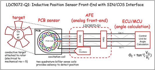
The LDC05072-Q1 is a front-end for inductive position sensors for measuring absolute rotary position in automotive and industrial applications. Inductive position sensors work on the principle of eddy current
generation and magnetic coupling. The LDC5072-Q1 connects to three inductive sensing coils that are usually on the printed-circuit board. One of the coils is connected to the exciter circuit of the LDC5072-Q1 (shown as the LC oscillator in the figure below) and acts as a transmitter, and the other two secondary coils are used as receivers. The transmitter coil induces a voltage in the secondary coils, which is a function of the position of the conductive target above the coils. The LDC5072-Q1 demodulates the signal received by the secondary coils and outputs a sine channel and a cosine waveform that represents the position of the conductive target above the sensor coils. An MCU can calculate the motor’s angle by performing an arctangent on the sine and cosine outputs as shown in the diagram just below.
A schematic of the analog portion of the system is shown below (from the EVM user's guide). A more detailed schematic can also be found there. A moving target will induce a modulated, time-varying magnetic field on the inductive sensors connected to device’s INxP and INxN pins, which will in turn cause sinusoidal signals to appear on the output pins’ COS channel (V(OUT0P,OUT0N)) and the SIN channel (V(OUT1P,OUT1N)).
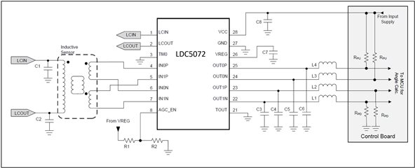
The schematic approximates the LDC5072-Q1 EVM , with the exception of the inductive sensors. These are not yet included in the EVM because system requirements usually prevent a “typical” sensor and target design that would be useful for prototyping. As an alternative, it is possible to design your own sensors and targets using the LDC5072-Q1 Sensor Design Tool. This a MATLAB-based tool that can be downloaded & installed from the LDC5072-Q1 product folder, requiring only an active myTI account and the completion of an export-approval form. The tool allows a user to enter their electrical and mechanical requirements, and it will then create a target and sensor design for the LDC5072-Q1, along with supporting Gerber files of the target, sensor, and an EVM layout. It is possible to create a pdf representation of the Gerber using easily available freeware that is available online.
The tool can also create a Spice model that allows a user to run Spice transient simulations of the design.
For more detailed information on the installation and capability of the tool, please see the LDC5072-Q1 Sensor Design Tool Getting Started Guide.
If any of the mechanical and electrical requirements are unknown, a design can be created that uses the default values of these input parameters in the tool. These values will propagate into the design’s layout, Gerber files and the Spice model.
A design based on the tool’s default settings results in sensor and target PCBs that resemble the figures shown below.
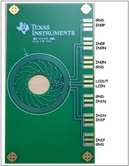
Note that the “sensor” PCB contains two input coils which connect to the LDC5072-Q1 INxN and INxP pins, and an exciter coil which is driven by the device’s LCOUT and LCIN pins.
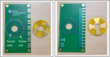
Note the register marks (↑) on the top layer of the sensor and target PCBs. They can serve as a useful reference point and can allow the user to precisely align the target with a known point on the sensor.
LDC5072-Q1 EVM – Add resonating caps and sensor PCB
The LDC5072-Q1 EVM is available for sample or purchase from the TI store. Details about the EVM can be found in the LDC5072-Q1 EVM User's Guide. The graphic below is taken from the user’s guide and it shows the major features on the EVM.
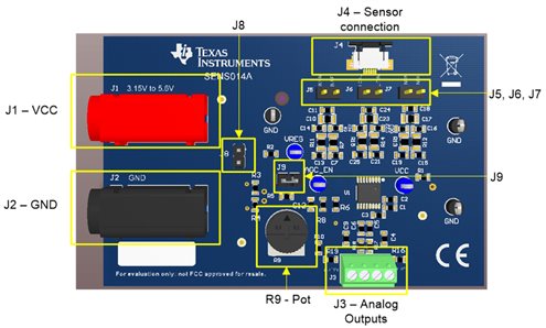
Note the EVM does not have sensor coils or a target, but these can be easily added via a design created by the LDC5072-Q1 Sensor Design Tool as mentioned above. The figure to the right is a sensor created by the design tool using the default values for all of the electrical and mechanical input parameters, and is included here only as an example. Note that a sensor coil PCB Gerbers created by the tool will not have labels on its connection points, so the labels are included in the figure just below for reference.
The remainder of this FAQ will give the steps to add the resonating capacitors to the EVM, and connect the sensor PCB to the EVM.
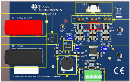
Step 1
The first step is to add capacitors to position C23 and/or C24 on the EVM. The capacitors will from a resonant LC circuit with the exciter coil. A good set of starting values are C23 = 33pF/50V and C24 = 330pF/50V. If these caps are not added, the exciter will not support a signal, and the device will go into a FAULT state.
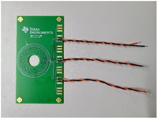
Step 2
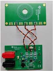
The next step is to solder wires to the sensor PCB as shown in the figure below and then twist the wires so they have 3-5 twists per inch.
Step 3
In the final step, connect the open end of the wired to the EVM as shown in the image below.
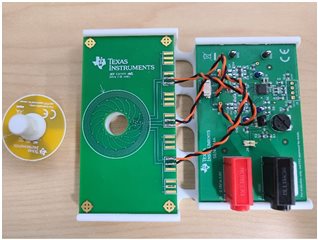
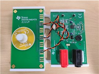
Step 4
In the final step, the PC boards should be mounted to a base and the target should be mounted on a spindle that can spin freely above the sensor coils without wobble and at the desired spacing between the target and coils. The images below show an example of a 3-D printed base and spindle.
Testing Your EVM
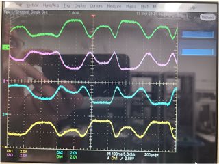
Once the connections are complete the rework can be tested by measuring the DC & AC voltages at some connections and test points on the board. The table below shows the approximate voltages you should see for various points on the board. The plot shows the OUTmn pins’ waveforms if you manually spin the target.
| Connection | DC Voltage |
| VREG | 3.3 Vdc |
| VCC | 5.0 Vdc |
| LCIN, LCOUT | 1.6 Vdc |
| IN0P, IN)N, IN1P, IN1N | 1.6 Vdc |
| OUT0P,OUT0N, OUT1P, OUT1N | 0.35V - 4.65V |