This thread has been locked.

If you have a related question, please click the "Ask a related question" button in the top right corner. The newly created question will be automatically linked to this question.

LDC1001-Q1: Proximity sensor

Part Number: LDC1001-Q1

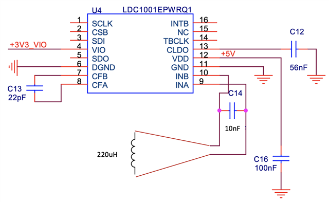
Hi all, I am using the TI LDC 1001-Q1 as proximity sensor to detect metallic objects. The LDC is connected to a Microcontroller and to an external squared coil with an inductance of 220uH (inner diameter/ outer diameter  = 0.86). The input capacitor is 10nF, resulting in an LC frequency of about 105 kHz. The LDC together with the microcontroller and other components, are soldered in a PCB, being only the coil external.

However, considering two identical PCBs (with LDC included), with the identical external coil and with the same firmware, I notice two different behaviours:
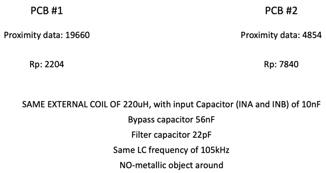
- One group of PCBs is working well, with a proximity data of 4500 when no metal object is on top , and Rp of about 8KOhm 

- Another group of PCBs is not working well, with a proximity data of about 18000 when no metal object is on top, and a resulting Rp of 2KOhm. 

In attachment you can find that the PCBs were programmed with the identical firmare (Rpmin, Rpmax, and the hardware is identical, with the same LC frequency) and the same coil is used for both of them.

For all the PCBs, I am using: 
1) Capacitor of 10nF between INA and INB

2) Bypass capacitor of 56nF

3) Filter capacitor of 22pF between CFA and CFB

Please could you help me in understanding the different behaviour of two nominally identical PCBs BUT with different proximity and the resulting different Rp ? What exactly influences the proximity value (considering for both the PCB that are in the same condition with no metal around and the same coil) ?

Please let me know,

Best,

Donato.


  • Hello Donato,

    Thank you for considering to use Texas Instruments.  I am looking into your inquiry now.  I will follow up later in the day if I have a possible hypothesis for your issue or with questions to help me narrow in on what might be the root cause of your issue.

  • Hello Donato,


    Its possible you are testing the manufacturing limits of your pcb manufacturer with your design. I think your coil might have a defect in it. You say that you are measuring a lower Rp for the defective boards, as such I am suspecting that a turn or so might be shorted together. To rule that out, there are a few options for what you can do.
    -Compare a good board coil and a bad board coil under a microscope to see if there is anything bridging turns in the inductor on the bad board.
    -Lift INA and INB pins then do a 4-wire resistance measurement of the coil (like the one mentioned here: https://cirris.com/4-wire-kelvin-testing/)
    -Swap device from a good board and put on a bad board and put the bad board device on the good board. If both boards continue to function as prior to the swap, then the inductor is more likely the issue.

  • Dear Patrick,

    Thanks for your feedback. However, the coil is external, so basically we have two sets of PCBs (good and "defective" ones), and we plug in the same external coil (plug/unplug), and we sistematically see the two different behaviours I mentioned, with the LDC detecting the metal for some boards (good) and not for others (defective, with much less sensitivity to a metal) even if everything else in the PCB is the same.

    In fact, both the good and the defective boards have basically the same LC frequency (of about 105kHz), so being the capacitor (C14 in the scheme above) the same (10nF), I would think that indeed the inductor is not the issue.

    Do you have any other idea on what could mostly affect the proximity data of the LDC1001Q (hence the Rp and the resulting sensibility) ? 
    1) Could it be due to the 10% tolerance of the capacitors (C12,13,14,16) ? In this case, what is the most critical capacitor in terms of the effect on the proximity? I tried to change the C14 with larger/lower values, a slight change on the LC frequency occurs in both the sets of PCBs, but still a remarkable difference in behaviour (between good and "defective") remains.

    2) Could it be due to some parasitic resistance due to the manual soldering of the capacitor C14 ? Even if for both the boards (good and defective) such soldering was done. May potentially  few Ohms difference of the contact resistance affect so strongly the Rp ?

    Please let me know if you can help us, since this issue is causing a delay on the large scale production of our solution based on the LDC1001Q.

    Thanks,

    Best,

    Donato.

  • Hello Donato,

    Thanks for providing those details.  I need to consult with my team.  I will try to determine a series of followup debug steps and/or provide a possible explanation for the phenomenon before close of business today.

  • Hello Donato,

    1-Using equation 2 in section 7.3.1 of the datasheet and the values in your schematic, I approximate rs (parasitic series resistance) to be about 2.81 ohm for the good board. If I use that rs value with a capacitor with +10% tolerance (11nF), I would get a lower Rp but still dramatically higher than the 2k you are observing.  So I am not completely convinced the tolerance is the issue, unless the ESR of the capacitor changes by a few ohms per tolerance.  C12 and C16 I do not expect to cause discrepancies of the magnitude you are seeing, so long as they are populated and roughly the same distance from the device on each board.  As for C13, you might consider a slightly larger capacitor.  Datasheet mentions something about sizing the capacitor such that the active filter doesn’t saturate and perhaps that is related to your issue.

     2-Perhaps the soldering could add to the cap ESR.  A few ohms of change could certainly shift the measured Rp.  It might not hurt to check the C14 cap connections and possibly give them a little more solder.

     Aside from the above mentioned.  I think it might be good to read back some of the values written to the registers to see if there are any discrepancies there.  Also if you can probe voltages on the LC tank with an oscope.  An active probe would be recommended or a passive probe with 1-kΩ series resistance between the tank and the probe would be good.  If you can share those scope shots, that might be helpful for me and my team too.  If all of those mentioned actions do not reveal any rogue behavior, it might be good to swap the LDC devices between the good and bad boards.  If the problem travels to opposite boards, then it might be device so long as registers and tank signals are verified to be performing as previously.