This thread has been locked.

If you have a related question, please click the "Ask a related question" button in the top right corner. The newly created question will be automatically linked to this question.

TMP61-Q1: TMP61-Q1

Part Number: TMP61-Q1

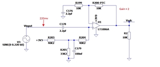
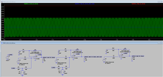
In the circuit in the figure below, we want to compensate the voltage gain according to the temperature variation. Since the input circuit (the V3 source) causes the output voltage to decrease with temperature variation, the idea is to use the PTC to increase the gain as the temperature rises.
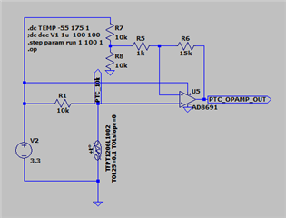
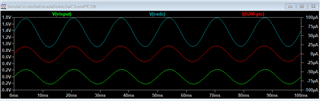
Our doubt is that at the point where we installed the PTC TMP61-Q1, (R200-PTC) in the drawing, although the opamp is DC only, the PTC suffers an "AC" maximum current of about +/-80µA. Could this be a problem?
Thank you in advance for your reply.
Thanks; Mauricio.
mauricio.correa@lupatecnologia.com.br

  • Dear Mauricio - 

    Instead of that method of sweeping - try using this similar circuit (for example) and short out C176 so the reference is DC grounded. 

    Gives you additional dynamic range over temp as you desire - the other way would be to use current source with the TMP6x devices, which allow about the same, so its a choice between using in Ibias mode vs. Vbias with OP amp.  

  • Thank you, Josh Wyatt, for your analysis.
    I think I failed to explain our intent.
    Or I didn't understand your answer correctly. Let me explain our question further: The source V3 in our circuit refers to an AC voltage that we want to measure. Although this voltage remains the same during generation, we can see that at the output of the circuit represented by source V3, this voltage decreases as the temperature increases. Also, since the voltage at the output of V3 is small, we have to give a gain to the AC signal, and since this signal enters the ADC of a microcontroller, we have to add a DC to the AC signal.
    So we took the opportunity to put the Texas PTC, whose part number is TMP6131QDYARQ1, on the gain and increase the output voltage as the temperature rises. The problem is that we can't find a position in the gain circuit where the current through the PTC is only DC instead of AC.
    Thanks again for your response. Mauricio

  • Mauricio - 

    You are correct, I completely misunderstood your intent.

    Are you trying to compensate the input signal, the opamp or both? 

    What is the 200mV source?

  • Josh;
    We want to compensate the input signal.
    The 200mV is the AC input signal (200mVac).
    The V3 source is a transformer where we have a fixed voltage on the primary, but this transformer is the one that is affected by temperature. On the secondary side we have an output of 200mVac. We try to compensate this input signal with the TMP6131QDYARQ1 PTC. In our tests so far, the compensation seems to work. Our concern is that since the current flowing through the PTC is AC and not DC, this is a big problem. And if you understand that there is a better way than this.
    Thank you very much for your efforts to help us.

  • Mauricio - 

    You may want to play around with the circuit like this: 

    Here, in the simulation, i used a similar 10k PTC that is in the tool 

    I changed the DC block and cap that provides AC ground to 10pF, the 2.2uF is too noisy IMHO. anyway, you can see the steps I took from the three circuits, where the last one has the first change and eliminates the pull up/tank circuit.. 

    Hope this helps you out. 

  • Hi Josh;
    Thanks for your attempts.
    We noticed that in your proposed circuit 2 and 3, we no longer have the AC signal at the opamp output, and so the microcontroller (which will be connected to the output of this circuit with the opamp) will not be able to calculate the RMS voltage of the signal.
    My conclusion after all this is that it doesn't seem to be possible to use the PTC in such a way that only DC current passes through it. In other words, we will always have AC current passing through the PTC.
    Since the Texas TMP6131QDYARQ1 PTC has polarity according to the datasheet, are we violating its operation?
    Do we risk burning out the PTC (which is polarized and should not receive AC according to the datasheet)?
    The Texas PTC model TMP6131QDYARQ1 does not accept this AC current passing through it? Or can we assume that this level of current would not be a problem for the TMP6131QDYARQ1?
    Below is the waveform of the current in the PTC and the input and output voltages from the original circuit.
    Thanks again for your help.

  • Mauricio - 

    OK. Let me take a look over the next day or so and I will see what I can help you further on. thanks for the additional details.

  • Okay, Josh;
    We'll wait.
    Just to remind you, we have already assembled the circuit with the PTC (physically) in our factory, and so far it is working as expected, with the only problem being that it is passing AC current through it instead of DC, according to the original circuit and waveforms above. Thank you very much.

  • OK - thanks