This thread has been locked.

If you have a related question, please click the "Ask a related question" button in the top right corner. The newly created question will be automatically linked to this question.

TMAG5170-Q1: Hall sensor measurement

Part Number: TMAG5170-Q1
Other Parts Discussed in Thread: TMAG5170

Hi, TI team

Does the 3D hall sensor TMAG5170-Q1 support the following application?

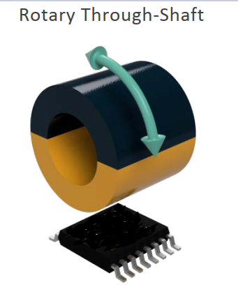
is there any difference compare to  the on shaft application, like the angle accuracy?

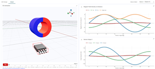
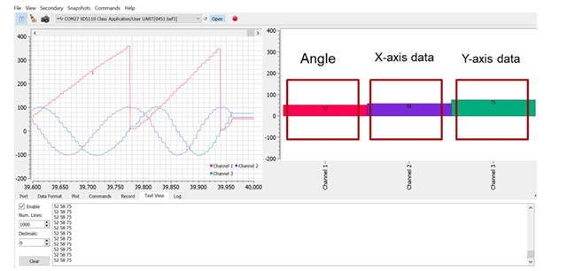
below is the on-shaft use case and the result from TI web site (3D Hall-Effect Sensor for Knobs in Appliances. (ti.com.cn))

thanks

  • Mat,

    Yes, the TMAG5170 can support the function shown above.  However, in that particular alignment there is typically an imbalance in the magnetic vector when separated into individual components.  The portion of the vector in the Z direction will be larger than the portion of the vector which is horizontal.  As a result the angle calculation will be non-linear without some adjustment.

    TMAG5170 has a sensitivity gain correction function which will help correct the amplitude mismatch of the two vector components and will help linearize the result.

    We do have a tool which can help to model this behavior. 
    https://webench.ti.com/timss/

    I created a sample configuration which you can explore with:

    OnShaft Rotation Example.json
    {
      "version": "3.1.3",
      "design_name": "",
      "magnet_id": 4,
      "poles": 2,
      "material_id": 1,
      "grade_id": 1,
      "select_remanence": "br_average",
      "remanence": 1200,
      "temperature": 20,
      "temperature_coefficient": -0.12,
      "coercivity": 10.9,
      "function_id": 1,
      "magnet_geometry": {
        "outer_diameter": 5,
        "inner_diameter": 3,
        "height": 4
      },
      "magnet_position": {
        "x_position": 0,
        "y_position": 0,
        "z_position": 0
      },
      "magnet_angle": {
        "x_angle": 0,
        "y_angle": 90,
        "z_angle": 0
      },
      "magnet_movement": {
        "arc_length": 360
      },
      "sim_setting": {
        "angular_step_size": 1
      },
      "sensor": [
        {
          "sensor_id": "TMAG5170",
          "sensor_position": {
            "x_position": 0,
            "y_position": 0,
            "z_position": -7
          },
          "sensor_angle": {
            "x_angle": 0,
            "y_angle": 0,
            "z_angle": 0
          },
          "custom_inputs": {
            "variant": "TMAG5170A2QDGKR",
            "applied_vcc": 3.3,
            "temperature_compensation": 0,
            "averaging": 1,
            "maximum_input": 75
          },
          "id": -1
        }
      ]
    }

    This .json can be imported directly by the tool.  After simulation, you can export the results to CSV for post processing.  To model the gain correction on the device you would need to calculate an arctangent using By and Bz.  By will need to be amplified by some factor (or Bz attenuated) so that the peak amplitudes match.

    Thanks,

    Scott