This thread has been locked.

If you have a related question, please click the "Ask a related question" button in the top right corner. The newly created question will be automatically linked to this question.

LDC1612: The questions and issues about using LDC1612 to measure distance

Part Number: LDC1612

Hello.

There are several questions when using LDC1612 to measure the height of different areas on coils and metal planes:

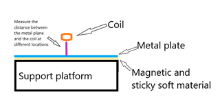
  1. There is a soft magnetic sticker under my metal plane to be measured, which is used to fix the metal plate, as shown in the picture. Will this soft magnetic sticker affect the LDC1612 measurement?
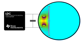
  2. Since the coil needs to be fixed, is there any metal that will not interfere with the LDC1612 measurement?
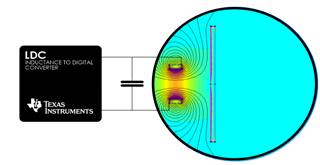
  3. Is there any requirement for the angle between the coil and the metal plane to be measured? Parallel is the best choice, but in reality there will be an inclination between the two?
  4. In order to reduce the impact of temperature on LDC1612, I use a temperature sensor to measure the temperature of the coil, and then design a compensation algorithm. How should I design a compensation algorithm?
  5. Since the metal plane has boundaries, measuring the center and edge of the metal plane should be different. Is there any way to resolve this difference?

A strange question:

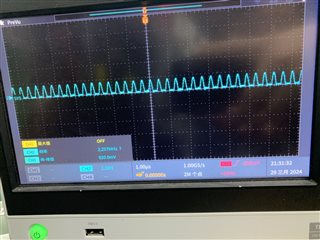
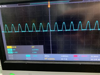
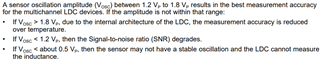
  1.   I found that when using LDC1612 to measure the height values of different areas and coils, there will always be a large error in a certain area (such as the upper left corner). The voltage Vosc at both ends of the coil has been confirmed to be between 1.2V~1.8V. What may be the cause?

Looking forward to your reply.

Thank you.

  • Hello, 

    Here are some answers to your questions:

    1. The LDC1612 is immune to the effects of any DC magnetic fields. Having the sticker behind the metal plate will not have any impact on the LDC1612's measurement. 
    2. Any conductive surface will have an impact on the coil but this impact is based on conductivity and distance to the sensor coil. Metals that are less conductive will couple less to the LDC1612's sensor coils. Additionally, metal directly behind the sensor (opposite the side of your intended target) is the biggest concern, especially if this metal is closer to your coil than the intended target. One thing you can do is to add a ferrite sheet between the coil and the unintended metal to prevent the coil from coupling to it. This helps focus the AC magnetic field from the sensor coil to the direction of your intended target. 
    3. There is no strict requirement. Just note that any angle in the metal target will decrease the coupling to the sensor coil and can create a shift in the measurement data. 
    4. You could create a lookup table of different temperature points for your application using the temperature sensor. Alternatively, if you are only using one channel of the LDC1612, you can create an identical coil on the second channel that does not look at a metal target. The identical coil will then only have the impacts from the environment (temperature) and can be used as a reference for your measurement. 
    5. The LDC1612's sensor coils generate an AC magnetic field that then forms eddy currents in the metal targets surface. Having the coil be near the edge of the metal target then impacts the formation of the eddy currents and causes a shift in the measurement. You would need to have some way of knowing weather the sensor coil is near the edge of the platform to be able to account for this. Otherwise, it could look similar to a shift in your target's distance in some cases. 
      1. I believe this effect of the eddy currents is also the cause for what you are seeing in your strange question. The sharp corner of the platform can have an additional impact on the eddy current formation and how it impacts the AC magnetic field. 

    Best Regards, 

    Justin Beigel

  • Hello.
    Thank you for your answer.
    There are still some doubts below

    1. Metal will only generate eddy currents on the surface near the coil, and there will be no reaction on the other side. Is that correct?
    2. Due to the presence of a metal plate in the middle, neither the sticker nor the metal under the metal plate will have any impact, as the magnetic field generated by the coil is blocked by the metal plate. Is this the case?
    3. Even if the ferrite sheet is in a magnetic field, it will not affect the measurement of LDC1612, is that so?
    4. Regarding the method of temperature compensation, I will conduct relevant experimental tests in the future. Thank you for your method.
    5. I will try my best to avoid using coils to measure the edge of the metal plate. Is there any way to confirm the range of the metal plate edge that cannot be measured? Currently, I am using the coil board of LDC1612 EVM.
    6. Regarding measurement accuracy and distance, is there a way to calculate the relationship between measurement accuracy and distance? Currently, I am using the same coil board as LDC612 EVM with 50% conversion time.
    7. Regarding the issue: LDC1612 has measurement errors at different positions on the metal plane. I avoided the edge area of the metal plate during testing, so it shouldn't be caused by the edges. At present, this issue has not been resolved. Do you have any other suggestions?
    8. When using LDC1612, I will modify the capacitance on the coil board and register configuration to ensure that the voltage Vosc at both ends of the coil is between 1V and 1.8V throughout the entire measurement range. My measure  range is 1-5mm. May I ask if there are any other things to pay attention to besides Vosc?

    Looking forward to your answer.
    Thank you.

  • Hello.

    Let me add an explanation of my testing method.
    I have built a mechanical mechanism for movement, which will move the metal plate up and down.
    At the same time, the coil plate will also move on the surface of the metal plate, and when the coil moves, the height of the metal plate remains unchanged.
    Here is my testing method:
      1. Select 9 points on the metal plate at equal intervals (avoiding the edges of the metal plate);
      2. Keep the height of the metal plate unchanged, move the coil above these 9 points, and measure a set of distance values;
      3. Modify the height of the metal plate (maintain within the range of 1-5mm);
      4. Follow step 2 to measure the distance values of the same 9 points at different heights;
    After multiple executions, I obtained many sets of height values for 9 points on the metal plane at different heights, and then analyzed and processed these data.
    Discovery: At individual points, the measurement error is significantly greater than at other positions. Some positions have an error of less than 0.01mm, while others have an error of 0.06mm.


    How to convert the output value of LDC1612 into a distance value:
      By changing the distance between the coil and the metal, the frequency value of LDC1612 at the corresponding distance is read to obtain a series of distance and frequency data. A mathematical relationship is obtained by fitting a 9-fold multiple similarity.

  • Hello Justin Beigel.

    Is there any simulation software available to view the magnetic field distribution of the coil and the interaction between the metal and the magnetic field?

  • Hello, 

    Metal will only generate eddy currents on the surface near the coil, and there will be no reaction on the other side. Is that correct?

    This depends on the frequency of the sensor coil and the thickness of the metal. Here is a simulation example of how the field density changes in the surface of a metal target close to a sensor coil:

    If you wanted to calculate it, you would need to determine the skin depth for your implementation based on sensor frequency and metal properties. Our LDC-CALCULATOR-TOOLS have a spreadsheet with a tab to help determine skin depths. For eddy current generation, 5 skin depths will be enough to give >95% current saturation in the surface, anything beyond 100% means that the eddy currents will not reach the other side of the metal plate. 

    Due to the presence of a metal plate in the middle, neither the sticker nor the metal under the metal plate will have any impact, as the magnetic field generated by the coil is blocked by the metal plate. Is this the case?

    Correct, the sticker or metal under the plate should not have any impact. 

    Even if the ferrite sheet is in a magnetic field, it will not affect the measurement of LDC1612, is that so?

    A ferrite sheet can act as a shield for the AC magnetic field and will not allow for eddy currents to build on its surface so it will not impact the LDC1612. 

    I will try my best to avoid using coils to measure the edge of the metal plate. Is there any way to confirm the range of the metal plate edge that cannot be measured? Currently, I am using the coil board of LDC1612 EVM.

    It seems like your application is leveling out your metal plate. If the plate height is not moving, you should see a much more significant shift in the data for the edge of the plate than for any variation in height of the plate. This article compares the difference in frequency shift for different target sizes for a given coil. I would recommend keeping the edge of the coil at least a few mm away from the edge of your metal plate for best results. 

    Regarding measurement accuracy and distance, is there a way to calculate the relationship between measurement accuracy and distance? Currently, I am using the same coil board as LDC612 EVM with 50% conversion time.

    Determining measurement distance accuracy can depend highly on the coil design and metal used. However, the general trend can be shown here: 

    The closer your coil is to your metal target, the more inductance change you will have for small motions. This leads to higher accuracy and being able to determine smaller differences in the metal distance. 

    Regarding the issue: LDC1612 has measurement errors at different positions on the metal plane. I avoided the edge area of the metal plate during testing, so it shouldn't be caused by the edges. At present, this issue has not been resolved. Do you have any other suggestions?

    What are you using for an RCOUNT value? increasing this helps with resolution but should be an all around case instead of per position. Additionally, is it the same positions every time that have higher noise or do the positions change with each test run? If it is same every time, are there any noise sources or other metals near those positions? 

    When using LDC1612, I will modify the capacitance on the coil board and register configuration to ensure that the voltage Vosc at both ends of the coil is between 1V and 1.8V throughout the entire measurement range. My measure  range is 1-5mm. May I ask if there are any other things to pay attention to besides Vosc?

    You will also want to make sure your deglitch filter setting is set properly for your sensor frequency. Beyond that, making sure SETTLECOUNT and RCOUNT are set properly for your sensor coil and desired resolution/sampling time. 

    Thanks for the clarification on the test case. When you move your coil plate, is there any change in the wire connection between the coil and the LDC1612 or are they both located on the moving plate? 

    There is an open source simulation tool called FEMM that you can use to do this. We have an application note that can help you get started with simulating an LDC coil in FEMM: Simulate Inductive Sensors Using FEMM (Finite Element Method Magnetics) (Rev. A)

    Additionally, our LDC-CALCULATOR-TOOLS have a spreadsheet that runs a FEMM simulation with your coil design parameters. If you input your coil design parameters in here and tell it to save the FEMM simulation, you can then open up the FEMM file and use it as a starting point to create your specific use case. 

    Best Regards, 
    Justin Beigel

  • Hello.

    About register configuration:

    1. In order to get higher accuracy, I used a 40M external crystal oscillator. Since I only need to use one channel (CH0), I set the conversion time of the other unused channel to be as small as possible.
    2. The following is the configuration of my registers:


           3. The following are the voltages Vosc across the coil when the distance is 0.1mm and the distance is 1.8mm.                                                

    Regarding the INTB signal, one additional point needs to be explained here:

    1. The original design is to capture the INTB signal through interrupts, confirm that the data conversion is completed, and then read the data.
      But for some reason, it is currently impossible to capture the INTB signal using interrupts, so I ignored it (continuously reading the data of the LDC1612), I'm not sure if this operation will cause problems?
    2. In addition, one thing has been confirmed before. When the INTB signal is triggered, the status register (0x18) needs to be read once before the INTB signal can be cleared and the next conversion can be performed. Is this true?

    About the test experiment:
        1. The LDC1612 and the coil board are connected through a wire of about 50mm length. They are fixed on the motion mechanism and move with the machine.
        2. The position deviation of each movement is <0.3mm. Compared with the diameter of the coil, I think the positions of the 9 points of each movement can be considered to be consistent.
        3. I checked several times. When the coil measured the distance, except for the metal plate under the coil, the other environment remained consistent to ensure that there would be no interference from other items.
        4. Judging from the captured waveform (as shown in the picture above), the frequency at both ends of Vosc is not greater than 3.3M, and no obvious noise interference is found.

    When using LDC1612, I summarized some ideas for troubleshooting:
    1. The frequency range and voltage range of Vosc at both ends of the coil, and whether there is noise;
    2. Register configuration, mainly the setting of sampling time, whether it meets the target accuracy;
    3. During use, are there any other objects that interfere with the magnetic field of the coil?
    4. The measurement distance is kept within 40% of the coil diameter to ensure high resolution (1um);
    Excuse me, is there anything else I need to pay attention to?

    Best Regards, 
    Max Chen.

  • Hello Max, 

    The original design is to capture the INTB signal through interrupts, confirm that the data conversion is completed, and then read the data.
    But for some reason, it is currently impossible to capture the INTB signal using interrupts, so I ignored it (continuously reading the data of the LDC1612), I'm not sure if this operation will cause problems?

    Reading the data like this is not a problem but I would recommend polling for the DRDY bit of the STATUS register to signal that new data is ready to be read from the data register. However, this may not be possible if your Ch1 is in an error state every sample window. Based on your configuration, it seems you are keeping both channels active and doing the Single-Channel Fref limitation work-around as described in section 3.2 of the Optimizing L Measurement Resolution for the LDC161x and LDC1101 app note. If you don't have an LC tank on the other sensor but keep it active, it will have an error on the channel 1 data which may be the reason your INTB is not flagging the DRDY bit as you expect. 

    In addition, one thing has been confirmed before. When the INTB signal is triggered, the status register (0x18) needs to be read once before the INTB signal can be cleared and the next conversion can be performed. Is this true?

    The next conversion will happen regardless of the status register read. If you do not read the status register fast enough, there is a chance that a data sample could be skipped. See figure 58 from the datasheet for an example of this. 

    In regards to your sensor waveforms, you dip below the 1.2V amplitude range on the low end so you may be getting a bit of increased noise there but it should be expected at all locations when the metal plate is close enough to cause the amplitude to be this low. 

    Beyond that, your configuration and test methodology seem good. One additional thing you could do is test a different set of 9 points or change the order that you test the same 9 spots to find a correlation if you are having issues with a specific area of measurement. 

    Best Regards, 

    Justin Beigel

  • Hello Justin.

    • About INTB:
      What will happen if I ignore the INTB signal and keep reading the LDC value? Will the value I read be wrong, or will the last converted value (old value) be read?
    • About the problem: The errors in measuring distance values in different areas of the metal plate are inconsistent.
      I did two experiments:
        1.1 The placement direction of the metal plate was adjusted, and the result: there was a significant difference in the measurement error;
        1.2 Using metal plates from another company, the result: the error improved significantly;
        Conclusion: At present, it seems that it may be related to the quality of the metal plate. The specific differences require further analysis.
    • How to ensure that the voltage at both ends of Vp meets the requirements within the measurement range?
      The current required measuring range is 0~5mm,
      1. When the distance is 0mm, the voltage across the coil Vp=960mv
      2. When the distance is 2mm, Vp = 2V
      3. When the distance is 3mm, Vp = 2.40V
      4. When the distance is 4mm, Vp = 2.64V
      5. When the distance is 5mm, Vp = 2.80V

                how to ensure that the voltage of Vp is between 1.2~1.8V within the full scale (0~5mm)?

                Looking at the information, it is recommended to use dynamic current, but in order to measure distance, a mathematical model will be established for the output value of the sensor and the distance value.
                Using dynamic current to adjust the voltage of Vp, I feel like it affects the math model, is that right? Is there any other way besides using dynamic current?

    • How to improve sensor accuracy?
      From the current data, the measurement accuracy of the sensor is related to the diameter of the coil. Is there any way to improve the accuracy of the sensor without increasing the diameter?

    Best Regards, 
    Max Chen.

  • Hello Max, 

    • Ignoring INTB will not have an impact on the LDC data. If you happen to read the STATUS register and DATA registers twice in the same sample window, then you will just get the same value twice. If you happen to miss an LDC conversion, then that data is just missed and the data you read will be the most recently completed LDC conversion data. 
    • Is the new metal plate a different material than the old plate? Did the old plate have any cracks or damage near the error areas? 
    • For the amplitude, we recommend between 1.2 and 1.8Vp for best accuracy. Above 1.8V leads to decreased accuracy over temperature. If  your application does not have much temperature swing and you are getting the resolution you need, then it is okay to continue to run at this level. If you adjust your IDRIVE setting so that you are at 1.8V max, then it would be important to make sure that your minimum amplitude does not decrease below 0.5Vp. This could cause the sensor oscillation to no longer be stable and return a 0 measurement. Between 1.2 and 0.5Vp, you may notice a bit more noise on the sensor. For more information on this, please see the Setting LDC1312/4, LDC1612/4, and LDC1101 Sensor Drive Configuration app note. 
    • For high resolution applications, we do not recommend using the automatic sensor drive current mode. When the sensor drive current changes, it can cause a sudden shift in the data that you would need to compensate for. Since your Z distance wouldn't be moving much during the 9 spot measurements, you may be able to set two different drive currents and break your 0-5mm range into two ranges with a known shift that will occur when you change the IDRIVE setting. 
    • There are a few things that can impact sensor accuracy/resolution: 
      • The RCOUNT setting - higher RCOUNT gives better resolution at the expense of a longer sample time
      • The reference clock - External reference clocks can have a better noise performance than the internal clock. In addition, making sure you have the proper clock divider set. It looks like you are already handling this one properly. 
      • Distance between the sensor and the target - The coupling between the sensor coil and the metal target will be much stronger when the two are close together causing a greater shift in the LDC data. Because of this, you can get higher resolution when the target and sensor coils are close together. This also plays into the diameter of the coil theory. A larger coil would have a larger sensing range and would experience a stronger field coupling at the 5mm end of your range. 

    Best Regards, 

    Justin Beigel

  • Hello Justin.

    Thank you for your answer.

    • Regarding ensuring that Vp meets the requirements:
      Could you please explain in detail how to solve the problem of the voltage at both ends of the coil not meeting 1.2-1.8V by setting different driving currents to divide two measurement intervals?
      During a measurement process, it may be required to simultaneously measure all distance values within the range of 0-5mm.
    • Regarding measurement accuracy:
      Thank you for your explanation. Increasing the conversion time, increasing the coil diameter, and reducing the measurement distance can improve measurement accuracy.
      Is there any other way to improve accuracy? For example, is it effective to use more layers of PCB boards to make coils, or to reduce the wire spacing of the coils?

    Best Regards, 
    Max Chen.

  • Hello Max, 

    For the Vp range, my suggestion is to calibrate your system for two IDRIVE settings. For your closer distances (0 - 2mm) set a slightly higher IDRIVE so your amplitude range does not dip much below 1.2V. Then calibrate the 2-5mm distances with a lower IDRIVE setting so your amplitude does not go much above 1.8V. You would need to switch between the two IDRIVEs with your MCU once you know the target is getting to the switch point. You could also overlap these two ranges if needed. 

    For the improved accuracy, the ways mentioned in my previous reply and the techniques in the Optimizing L Measurement Resolution for the LDC161x and LDC1101 app note are the only things that will impact it. If your sensor does not already have a high Q factor, then changing the coil properties may help. But if your sensor coil Q factor is already above 30, I wouldn't expect much impact. As for your two examples, additional PCB layers slightly add to the EM field that couples the metal to the sensor coil but won't make a considerable enough difference to impact resolution. Same goes for the wire spacing or number of turns in the coil. 

    Best Regards, 

    Justin Beigel