This thread has been locked.

If you have a related question, please click the "Ask a related question" button in the top right corner. The newly created question will be automatically linked to this question.

TMCS1107-Q1: AC Load Current Measurement.

Part Number: TMCS1107-Q1
Other Parts Discussed in Thread: TMCS1107

Hello,

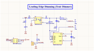
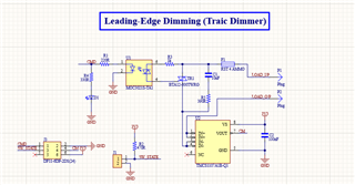
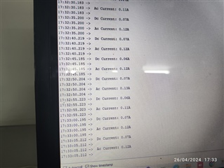
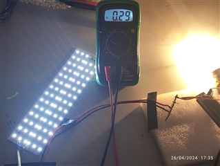
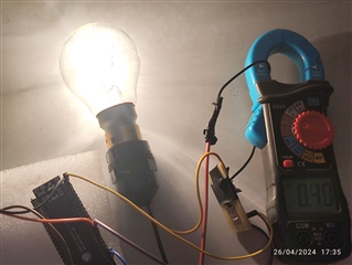
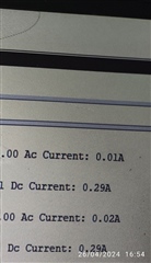
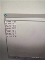
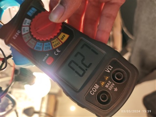
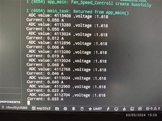
I am utilizing the TMCS1107A1BQDRQ1 IC for measuring current in both AC and DC loads. When testing DC load, I observed that the output voltage of the IC change depending on whether the device is powered on or off. However, when testing AC load, I consistently measured a voltage 1.65 at output of IC regardless of device power status. I want to measure the current on the AC line of Bulb and fan by using the schematics given below, but I couldn't. I got 1.65 by using this 0.5 × VS (VS=3V3) which is mentioned in datasheet.

  • Hello,

    Could you tell me more about how you got these results? Did you make these measurements using only the simulation, or was this tested using the actual device? I also noticed that you are using the incorrect device in your simulation here - you said you were using the TMCS1107A1B, while the simulation is using the TMCS1108A1U. When you say "The device is powered on or off" do you mean the TMCS1107 or do you mean the AC/DC load? If you are seeing a voltage output on the device without power being applied please check to ensure there is no voltage on the device pins.

    Thank you,

    Levi DeVries

  • Hello Levi,

    Thank you for your reply and bringing this to my attention. I made measurement on actual AC device for resistive load I used bulb and for inductive load I used fan, and I am using TMCS1107A1B IC for measurement I applied a 3.3V input to the IC and controlled the AC device on and off condition, I consistently measured a voltage of 1. 65V or 1. 64V.However, when testing with DC load, I observed a change in voltage during both on and off conditions of load. I also compared the current measurement taken by an IC and a multimeter and found that they were almost same. However, when comparing the measurement in AC, I was unable to obtain accurate results. I then compared the measurement with a clamp on meter and found a significant difference between the reading obtained by IC and the clamp on meter. Interestingly the voltage remained the same in both on and off ac conditions of loads. 

    Case: -1

    The above schematic has been created to meet the specific requirements of my project. The AC load is connected to this module, and I am measuring the current of load. 

    Case: -2

    I made same circuit which is given in guideline and again actual  I tested AC load bulb and fan but I got same result as I mention above I got 1.65V or 1.64V during on and off conditions of load. 

  • Hello,

    The TMCS1107A1B should output a voltage that is half the supply voltage when the device is powered but is measuring no current, so the average AC voltage should be 1.65V when you are powering the device with 3.3V. So if you are averaging the output of the device you will see the voltage look like a constant 1.65V. Is this how you are measuring the output?

    Let me know if this solves your issue,

    Levi DeVries

  • I am not averaging the output I am simply measured output voltage of current measuring IC through multimeter. Below are the testing results for both AC and DC.


    The image above shows the device being turned off, and current measuring using multimeter and clamp on meter is also zero.

    Th image above shows current measurements taken by the TMCS1107A1B IC under off conditions of both AC and DC loads.

    The following images depict the on conditions of both AC and DC loads. I obtain precise measurements for DC, but I couldn't get in AC. 

    The code is provided below.


    // Accumulate 100 samples
    for (int i = 0; i < 100; i++) {
    int adc_value = analogRead(sensorPin);
    sum += adc_value; // Accumulate ADC values
    delay(20); // Delay between samples
    }

    // Calculate average ADC value
    float avg = sum / 100.0;

    // Calculate voltage
    voltage = avg * (3.3 / 4095.0);

    float Voltage_AfterZero = (voltage - 1.65).
    // Convert voltage to current
    float Current = (Voltage_AfterZero) / 0.05.

    First, I read adc pin which is connected to output pin of ic  and then using voltage equation adc value is convert into voltage and after converting whatever voltage is obtain is minus from 1.65 (0.5*3.3V) which is given in datasheet and this voltage converted in to current.   

  • Hello,

    I see that you are using an onboard ADC to read the IC output voltage with a microcontroller. What sample frequency are you using with the ADC? I am also assuming that the AC signal you are using is a 60Hz signal, please correct me if I am wrong.

    Thanks,

    Levi DeVries

  • Hello,

    My AC signal is of 50HZ. I tested at two different sampling frequencies 50Hz and 100Hz. Please provide the Arduino code for AC load current measuring.

    Thanks,

  • Vanshika,

    Looking at your code, it looks like you are averaging your samples 100 at a time here: 

    // Calculate average ADC value
    float avg = sum / 100.0;

    In order to measure AC current, simple averaging will cause the measurement to appear as zero because AC signals are centered around zero. Most meters use RMS measurements to measure a value for current, so your clamp meter is most likely using RMS measurements. Whether this is appropriate for your application must be determined by you, but you can make a few modifications to your code to change your measurement to an RMS measurement:

    int adc_value = analogRead(sensorPin);

    Here you should convert the measurement to a voltage immediately and subtract the 1.65V midsupply value so that it will read:

    float adc_value = analogRead(sensorPin) * (3.3 / 4095.0);
    adc_value -= 1.65;

    and square the measurement:

    adc_value *= adc_value;

    Then after you are done averaging the signal, you should take the square root of the signal:

    voltage = sqrt(avg);

    Furthermore, if you are collecting samples at 50SPS or 100 SPS you will probably see some adverse effects of sampling at frequencies too close to the frequency of the signal you are trying to measure - you may end up sampling all the zero-crossings, or all the peaks, or all the troughs of the sine wave. It would be better if you sampled at a frequency unrelated to the signal, such as 75SPS.

    Let me know if you need any more help with this,

    Levi DeVries

  • Hello,

    Base on your suggestion, I averaged the signal and then took, the square root, resulting in a perfect outcome . However, I tested this on the on-board ADC of ESP32 S3, the results were perfect .In my project I am using LTC2497 ADC and when I tested it  the outcome was not perfect . Additionally the datarate  at which the LTC2497 ADC samples is 7.5sps. 

    On borad Adc Code

    #define SENSITIVITY 0.05
    #define RESOLUTION 4095.0
    #define VRF 3.3

    int calibrate()
    {
    int _zero = 0;
    for (int i = 0; i < 10; i++)
    {
    _zero += analogRead(Adc_Pin);
    delay(200);
    }
    _zero /= 10;
    zero = _zero;
    return _zero;
    }

    float getCurrentAC()
    {

    uint32_t Isum = 0, measurements_count = 0;
    int32_t Inow;
    for (int i = 0; i < 100; i++)
    {
    Inow = zero - analogRead(Adc_Pin);
    Isum += Inow * Inow;
    measurements_count++;
    delay(200);
    }


    float Irms = sqrt(Isum / measurements_count) / RESOLUTION * VRF / SENSITIVITY;

    return Irms;
    }

    The image below display the result of testing conducted on the on board ADC of ESP32 S3 and compare it with result of clamp on meter both are almost same.

    LTC2497 Code

    #define SENSITIVITY 0.05
    #define RESOLUTION 8388608.0
    #define VRF 3.3

    void read_register_data(uint8_t reg, uint8_t *buffer, size_t len)
    {

    esp_err_t err = i2c_master_write_read_device(I2C_PORT, LTC2497, &reg, 1, buffer, len, 1000 / portTICK_PERIOD_MS);
    if (err != ESP_OK)
    {
    printf("Error occurred during Reading Register 0x%02X\n", reg);
    }

    }

    int calibrate()
    {
    int _zero = 0;
    for (int i = 0; i < 20; i++)
    {
    read_register_data(reg, buffer, sizeof(buffer));

    // check -1LSB bit for negative
    if ((buffer[0] & 0b01111111) == 0b01111111)
    {
    buffer[0] = 0x00;
    }
    // Extract the ADC value from the buffer
    int Zero_value = ((((buffer[0] & 0x3F)) << 16)) + ((buffer[1] << 8)) + (((buffer[2] & 0xE0)));
    _zero += (Zero_value / 20);
    vTaskDelay(150/ portTICK_PERIOD_MS);
    }
    _zero /= 20;
    zero = _zero;
    printf(" zero value: %d\n", zero);
    return _zero;
    }

    float getCurrentAC()
    {
    uint32_t Isum = 0, measurements_count = 0;
    int32_t Inow;

    for (int i = 0; i < 100; i++)
    {
    // Extract the ADC value from the buffer
    read_register_data(reg, buffer, sizeof(buffer));

    // check -1LSB bit for negative
    if ((buffer[0] & 0b01111111) == 0b01111111)
    {
    buffer[0] = 0x00;
    }

    // Extract the ADC value from the buffer

    int32_t adc_value = ((((buffer[0] & 0x3F)) << 16)) + ((buffer[1] << 8)) + (((buffer[2] & 0xE0)));
    Inow = zero - adc_value;
    Isum += Inow * Inow;
    measurements_count++;
    vTaskDelay(150 / portTICK_PERIOD_MS);
    }

    float Irms = sqrt(Isum / measurements_count) / Res * vrf / sensitivity;
    return Irms;
    }

    The LTC2497 ADC Conversion Time is 149.9mS,therefore a delay of 150  is required.

    The image below display the result of testing conducted on the LTC2497 ADC and compare it with result of clamp on meter both are not  same.

    The AC signal has a voltage of 230V and 50Hz.

    I have doubt about the data rate  of 7.5sps, therefore it is not possible to obtain perfect  current measurement using LTC2497 ADC.


  • Hello Vanshika,

    I have doubt about the data rate  of 7.5sps, therefore it is not possible to obtain perfect  current measurement using LTC2497 ADC.

    Actually, I don't think your sample rate will impact measurements at all, it will just take measurements slowly. I suspect any inconsistencies are being caused by code errors or system constraints you are unaware of.

    As a note, I don't know how the following code block is supposed to work:

    // check -1LSB bit for negative
    if ((buffer[0] & 0b01111111) == 0b01111111)
    {
    buffer[0] = 0x00;
    }

    but it will only run when buffer[0] == 0b01111111 or buffer[0] == 0b11111111.

    Let me know if you have any more questions,

    Levi DeVries