This thread has been locked.

If you have a related question, please click the "Ask a related question" button in the top right corner. The newly created question will be automatically linked to this question.

TMAG5170: Rotary knob design and best sensor

Part Number: TMAG5170
Other Parts Discussed in Thread: TMAG5173-Q1, , TMAG3001, TMAG5273

Hello,

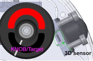
I am designing a rotary knob and would like to use a 3D Hall Effect Sensor.  The knob is used to control variable speed of a motor.  I am currently using a potentiometer but looking to refine my design/assembly.

Mechanically the knob will be limited between 0~300 degrees.  I plan to use a diametric ring magnet attached to the knob.  The target will likely be off the center axis of the target and a few mm off the face of the sensor.  Attached is a screen of a rough layout.  I plan to test different targets and mechanical positions to determine what works for my system requirements.

Is the TMAG 5170 the sensor I should be looking at or do you have other suggestions?  Ideally I can use a dev kit to easily test/verify the design before developing my integrated solution - do you have recommendations for this?


Regards

  • Michael,

    A 3D Hall-effect sensor would work well here.  TMAG5170 would certainly be a good choice, but you might also consider TMAG5173-Q1, TMAG5273, or TMAG3001.  All of these devices have an evaluation kit that you should be able to do some prototype testing with. You will want to get the respective EVM along with the TI-SCB

    What you'll find in this location is that the two components of the field you use to calculate angle (it might make sense to use Z with either X or Y depending on placement) is that there will likely be some amplitude mismatch of the output sine and cosine signals you measure.  This can cause non-linearity in the output measurement, so you will want to do some gain correction to get a matched amplitude.  All of these devices offer a way to adjust the sensitivity gain to do this for you on-chip.  They also then can use that adjusted output to generate an angle calculation.

    You might also find that if you are placing the sensor very close to the magnet that there can be some distortion observed from the desired pure sine and cosine waveforms you want to calculate angle.  If you observe this, it might be helpful to increase range to the magnet.  This distortion can also cause angle non-linearity in the calculated result.  Otherwise you may find yourself needing to do some calibration to account for this.

    thanks,

    Scott

  • Thank you for the quick response.

    At a high level what are the considerations between the 5170, 5273, and 3001?

    When you say calibration for non linearity - is this a per unit basis or more of a general development? I figure its the latter.

  • Michael,

    TMAG5170 is in the largest package (VSSOP) and communicates over SPI

    TMAG5273 is in a SOT-23 package and communicates of I2C

    TMAG3001 is a WCSP package and also communicates over I2C.

    A non-linearity calibration will be best unit to unit, but if you are able to repeatably install the magnet with the same alignment from unit to unit, then you might do well enough with a general calibration.  Your goal in application will be to place the sensor close enough to the magnet to get good SNR, but not so close to saturate the inputs or pick-up distortion caused by the shape of the magnet.

    What you'll likely find is that the larger radius ring magnets will be more prone to the distortion I mentioned previously. What might help explore is to use our simulator tool here:

    https://webench.ti.com/timss/

    Thanks,

    Scott