Other Parts Discussed in Thread: AWR6843AOPEVM,
Hi,
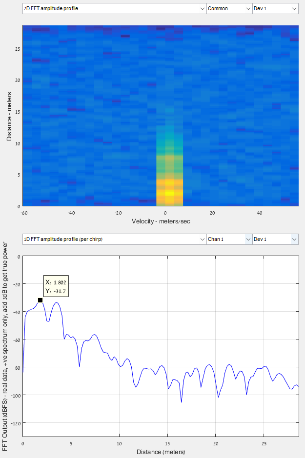
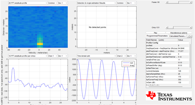
Enclosed is an image (screenshot from mmwave studio 3) displaying a measurement of 21.78dBsm corner, 1.8 meters distant from the radar.
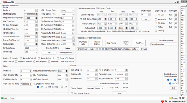
Below, you'll find a Python code containing all parameters pertinent to the chirp configuration.
The image reveals a detection of -31.7dBFS at the corner, a deviation from the anticipated theoretical value of -7.6dBFS.
Although the user guide specifies an antenna gain of 15dBi, this value isn't evident in the measured outcome.
Your assistance in resolving this matter is greatly appreciated.
Thank you,
Shlomi
Result:
Pr = 2.4 [dBm] OR -7.6 [dBFS]
Python code:
def db2lin(x_db):
    return 10 ** (x_db / 10)
def lin2db(x):
    return 10*np.log10(x)
def lin2dbm(x):
    return lin2db(x) + 30
def dbm2FS(x_dbm):
    return x_dbm - 10
c_ms = 299792458
sigma_dbsm = 21.78
fc = 77e9
Pt_dBm = 12
Gt_dB = 15
Gr_dB = 15
R_m = 1.8
Ramp_End_Time = 11e-6
ADC_Start_Time = 5.12e-6
Nc = 31
NF_dB = 13
L_dB = 10
RX_gain_dB = 30
ToT = Nc*(Ramp_End_Time - ADC_Start_Time)
lambda_m = c_ms/fc
Pt = dbm2lin(Pt_dBm)
Gt = db2lin(Gt_dB)
Gr = db2lin(Gr_dB)
sigma = db2lin(sigma_dbsm)
NF = db2lin(NF_dB)
L = db2lin(L_dB)
RX_gain = db2lin(RX_gain_dB)
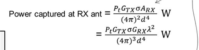
Pr_lin = Pt * Gt * Gr * lambda_m**2 * sigma / ( (4*np.pi)**3 * R_m**4 ) * RX_gain
Pr_dBm = lin2dbm(Pr_lin)
Pr_dBFS = dbm2FS(Pr_dBm)