This thread has been locked.

If you have a related question, please click the "Ask a related question" button in the top right corner. The newly created question will be automatically linked to this question.

AFE3010: AFE3010 - Trip current variation with respect to Line Volatge

Part Number: AFE3010

Hi,

We have designed GFCI Circuit for our EV charger product & the AC power input t is 208/240VAC 60Hz [L1 to L2] US region.

We have set the Trip current value to 18-20mArms & we have been facing issue that the Trip current is not stable at change in Supply voltage. The trip current keeps varying when the AC voltage is varied.

Ex: Trip current set to 18mArms at 240VAC trips at 14mArms at 208VAC. 

We have following Questions,

1. Will the Chip work for 208 to 240VAC 60Hz ? The datasheet mentions it Supports 120-V/ 60-Hz or 220-V/ 50-Hz systems.

2. Will the Chip work on 20VDC Power supply [VDD1 & VDD2]? Instead of powering it from AC followed by Bridge rectifier ? We tried to power it up from 20VDC power supply but the Self test fails.

3. What is the voltage of VTH:1-4 ?

4. Since the System works on L1 to L2 208/240VAC, Adding the current limiting resistor [R177] at the L2, fails the circuit. Does the Current limiting resistor not needed on L2 line ?

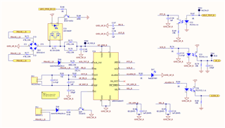
Below is our Schematics, We have been working on to tune the Burden resistor & Trip current value [R181 & R182 respectively].

  • Hello Appreciated Engineer,

    I have not seen this issue.

    1. The chip can indeed work on this range.

    2. VDD pins can be powered with a separate DC 20V source, but you need to make sure it can achieve a decent power up time. Also, you won't need much or any current limiting resistors with this method.

    3. I assume you mean threshold voltages for four internal comparators. 

    Vth high4 4.80
    Vth high3 3.85
    Vth high2 2.95
    Vth high1 2.75
    REF 2.50
    Vth high1 2.25
    Vth high2 2.05
    Vth high3 1.10
    Vth high4 0.20

    4.The current limiting resistor is not needed for L2, In fact, its presence could be causing an issue with the diode detection self test. I need to investigate this more.

    How are you measuring a 14mA trip level? Do you see the ALARM blinking after trip current detected? Can you please slowly increase fault currents in small increments and wait at least 5 seconds to make sure device is not failing a self test?

    What is power up time for 20X source?

    Any scope shots of L1/L2, SCR, VDD, and OUT would be helpful.

    Sincerely,

    Peter

  • 1. How are you measuring a 14mA trip level?

    We have connected Multimeter in series between L1 of Load & Potentiometer connected to Protective Earth. We are Leaking the current to Earth by reducing the resistance between L1 of Load & PE via Potentiometer.

    2. Do you see the ALARM blinking after trip current detected?

    We see the ALARM LED only during Self test. During the actual current leakage simulation test [Field scenario], we turn off the 20V power supply to the chip as soon as we get SCR Interrupt. This is due to a test case - Multiple trip/Continuous Leakage current. 

    Below is the sequence,

    For self test,

    Power on the Source to Chip ---> Wait for 400ms ---> Perform self test ---> SCR triggered / Alarm LED Blinks.

    For Actual current leakage simulation test,

    Power on the Source to Chip ---> Wait for 400ms ---> Perform self test ---> SCR triggered / Alarm LED Blinks ---> Turn on the Load ---> reduce the resistance between L1 of Load & Earth via potentiometer [till 17.5mA threshold] ---> SCR triggered ---> Turned off the power source to chip [as soon SCR Interrupt is triggered] ---> Wait for 1 Second ---> Turn on the Power Source ---> 17.5mA leakage still present [here we are not doing self test] ---> SCR triggered ---> Continuous leakage ---> Power Recycle the system/Unplug the Plug from vehicle.

    3. What is power up time for 20X source?

    During Self test, we wait for 400mS to do Self test after Power up. 

    4.Any scope shots of L1/L2, SCR, VDD, and OUT would be helpful.

    We currently don't have isolated probe to measure high voltage, we will do this & share with you.

  • Hello,

    A. How are you performing self test?

    B. When you do perform a successful self-test, does the ALARM only blink once, or does it keep blinking at 0.5Hz?

    C. Why do you perform a self-test 400ms after power up? The device automatically does this 60 cycles (1 second) after power up.

    D. Just to confirm, you do have a stable system? By stable system I mean, you power up the AFE3010 and 1 second later you see the ALARM LED blink only one single time and never again for at least 1 minute? This should happen with no leakage and no external self testing using PTT/SW_OPEN).

    E. Can you please repeat the test, but do not disconnect VDD power once SCR is triggered? I just want to know if the ALARM blinks continuously after this even to rule out some self-test failure that is making it look like a premature ground fault tripping.

    There could be an issue with VDD not receiving enough supply current when line is dropped to 208VAC. To test this, I recommend decreasing R172, R173, and R176 so that the total RC time constant ( (R172+R173||R176)*3.3uF ) < 0.08 at least. Good values for this RC are less than 0.065 in order to achieve fast enough trip times (<~25ms) for the UL943 required 500-Ω leakage fault conditions on power up (not sure if that is a requirement for you here). Obviously short out R177 if the presence of this is causing self-test fails. Either way, I think this would be a good start to rule out that there is not a power issue here.

    Another slight simplifying modification to make is increasing R183 to R184. 1k||1k is a low resistance for ALARM to drive and pull significant current from internal supply. I recommend increasing both resistors to 10k (or whatever is high but still low enough to generate sufficient luminescence in D37 and U26. 

    Also please try to populate the noise blocking capacitors C116 and C117 at SW_OPEN and SEL pins to just to rule out any noise issue.

    Sincerely,

    Peter