This thread has been locked.

If you have a related question, please click the "Ask a related question" button in the top right corner. The newly created question will be automatically linked to this question.

TMP411-Q1: Remote diode sensor design

Part Number: TMP411-Q1

Tool/software:

I would like to ask about the details of the circuit design of the temperature sensor:

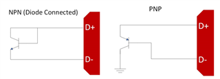
The first question is when selecting a remote diode sensor, most designs use NPN or PNP transistors, why not just use ordinary diodes? Both are based on the relationship between PN junction forward voltage drop and temperature.

The second question is why the base and collector connections D+ and D − of the transistor are not chosen in the design, but the base and emitter are generally chosen?

  • Hello Mike,

    Our Remote sensors are calibrated for transistors with a stable η-factor of 1.008. TI can not disclose information about details of the circuit design. In regards to connecting D+ and D-, I have attached a diagram showing two different methods in connecting to the junction. Both methods are valid. The method of choice is based on preference.

    Best Regards,

    Meredith McKean