This thread has been locked.

If you have a related question, please click the "Ask a related question" button in the top right corner. The newly created question will be automatically linked to this question.

UCC28C43: UCC28C43DGKR

Part Number: UCC28C43

Tool/software:

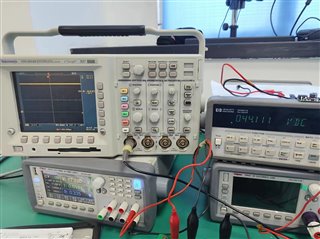
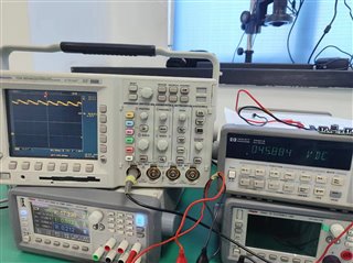
This product is used to boost the working mode, the boost value is 44V, after loading the product in this batch of products in the under-voltage opening of the output superimposed 5V triangle waveform, previous batches of DC voltage,Can you see what the reason is, please

  • Please describe more accurately about the issue you are seeing? Both pictures seems to be almost no ,load but what is the desired max load? What is the schematic? Does the "triangle" waveform change with input voltage or load and if so what are the test conditions? What type of boost, bulk capacitor(s) are being used and what is the max RMS rated current compared to the RMS pulsed output current?

    Regards,

    Steve

  • 1. The waveform appears at the opening voltage of the product in no load and disappears with the increase of the input voltage or after loading. 2. The opening voltage is turned on and off by the output of the external comparator through a diode to pull down the circuit pin 1. The triangle wave is related to the small hysteresis set by the comparator. Our question is why the triangle waveform did not appear in previous batches and the triangle wave amplitude reached five or six volts. 3. The input and output capacitors of the booster circuit are 10UF50 volt ceramic capacitors, and the output current at full load is 100 mA.

  • Please provide a schematic and if you could capture a waveform of the no load startup (VIN, VOUT, IL) and also capture the behavior of COMP as the converter transitions in/out of the mode we are discussing.

    Steve