This thread has been locked.

If you have a related question, please click the "Ask a related question" button in the top right corner. The newly created question will be automatically linked to this question.

AWR2243: Real sampling

Part Number: AWR2243

Tool/software:

Hi,

  I have a question.

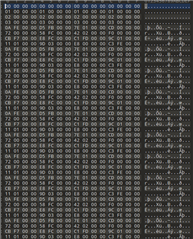
When I configured the ADC acquisition for complex sampling, the data collected by CSI2 was in the correct format.

When I configured the real sample, the data format was wrong.

I want to know what is the output data format of the real sample?

  • Hello dongsheng,

    You can refer this document: https://www.ti.com/lit/an/swra555a/swra555a.pdf
    In section 2.1.2.1  and 2.1.2.2 you can see how the arranging of data would be done.

    Regards,
    Saswat Kumar

  • Thank you for your answer.

    I use  CP_ADC_DATA format,
    I want to know the format of CP data in the case of real sampling.

  • Hello dognsheng,

    CP does not matter on whether it real or not.
    Based on the interleaving and type of ADC data. you get the ADC data packet.
    The CP data is before that packet always. It is not impacted by your packet.
    The document I shared provides a detailed overview, you can understand a lot more details once you go through it.

    Regards,
    Saswat Kumar

  • Why did I set up a real sample, 1024 sampling points, only 512 ADC data is valid?
    Here is my configuration file:

    #####################################################################################
    #power on master arguments, please modify if needed.
    #rlClientCbs_t: crcType 0:16Bit/1:32Bit/2:64Bit, ackTimeout
    #
    crcType=1;
    ackTimeout=1000;
    #END

    #####################################################################################
    #channel config parameters, please modify if needed.
    #rlChanCfg_t
    #
    channelTx=7;
    channelRx=15;
    cascading=0;
    #END

    #####################################################################################
    #ADC out config parameters, please modify if needed.
    #rlAdcOutCfg_t Real
    #
    adcBits=2;
    adcFormat=0;
    #END

    #####################################################################################
    #DATA format config parameters, please modify if needed.
    #rlDevDataFmtCfg_t
    #
    rxChanEn=15;
    adcBitsD=2;
    adcFmt=0;
    iqSwapSel=0;
    chInterleave=0;
    #END

    #####################################################################################
    #Low power config Paramters, please modify if needed.
    #rlLowPowerModeCfg_t
    #
    anaCfg=0;
    lpAdcMode=0;
    #END

    #####################################################################################
    #Data Path config parameters, please modify if needed
    #rlDevDataPathCfg_t
    #
    intfSel=0;
    transferFmtPkt0=6;
    transferFmtPkt1=0;
    cqConfig=2;
    cq0TransSize=132;
    cq1TransSize=132;
    cq2TransSize=72;
    #END

    #####################################################################################
    #LVDS clock config parameters, please modify if needed
    #rlDevDataPathClkCfg_t
    #
    laneClk=1;
    dataRate=1;
    #END

    #####################################################################################
    #SET HSI clock parameters, please modify if needed.
    #rlDevHsiClk_t 0xd 13 900M
    #
    hsiClk=9
    #END

    #####################################################################################
    #LANE config parameters, please modify if needed.
    #rlDevLaneEnable_t
    #
    laneEn=15;
    #END

    #####################################################################################
    #LVDS Lane Config parameters, please modify if needed.
    #rlDevLvdsLaneCfg_t
    #
    laneFmtMap=0;
    laneParamCfg=1;
    #END

    #####################################################################################
    #CSI2 Lane Config parameters, please modify if needed.
    #rlDevCsi2Cfg_t
    # 0x35421
    lanePosPolSel=218145;
    #END

    #####################################################################################
    #Programmable Filter config parameters, please modify if needed.
    #rlRfProgFiltConf_t
    #
    profileId=0;
    coeffStartIdx=0;
    progFiltLen=14;
    progFiltFreqShift=100;
    #END

    #####################################################################################
    #Profile config parameters, please modify if needed.
    #rlProfileCfg_t
    #
    profileId=0;
    pfVcoSelect=0;
    startFreqConst=1422339870;
    idleTimeConst=3200;
    adcStartTimeConst=249;
    rampEndTime=3000;
    txOutPowerBackoffCode=0;
    txPhaseShifter=0;
    freqSlopeConst=207;
    txStartTime=0;
    numAdcSamples=1024;
    digOutSampleRate=37500;
    hpfCornerFreq1=0;
    hpfCornerFreq2=0;
    rxGain=30;
    #END

    #####################################################################################
    #Frame configuration parameters, please modify if needed.
    #rlFrameCfg_t
    #
    chirpStartIdxFCF=0;
    chirpEndIdxFCF=383;
    frameCount=1;
    loopCount=1;
    periodicity=10000000;
    triggerDelay=0;
    numAdcSamples=1024;
    triggerSelect=1;
    #END

  • Hello dongsheng,

    I did not understand your question, please do rephrase.

    Why did I set up a real sample, 1024 sampling points, only 512 ADC data is valid?

    Regards,
    Saswat Kumar