


Other Parts Discussed in Thread: PGA460
Tool/software:
Hello everyone,
I have a PGA460-Q1 driver and it's connected in the following circuit:
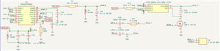
Explaining the circuit:
- I am communicating with the PGA460 via UART using an STM32 microcontroller
- The transformer used is the B78416A2430A003 which has a 1:1:15 turn ratio. The center tap is connected to 5V and the other extremities are connected to OUTA and OUTB of the driver
The configuration sent to the registers of the PGA460 is as following:
#define TVGAIN0 0x00
#define TVGAIN1 0x00
#define TVGAIN2 0x00
#define TVGAIN3 0xFF
#define TVGAIN4 0xFF
#define TVGAIN5 0xFF
#define TVGAIN6 0xFC
#define INIT_GAIN 0x00
#define FREQUENCY 0x2D//0x64//0x2D
#define DEADTIME 0x00
#define PULSE_P1 0x7F//0x61//0xDF//0xC1
#define PULSE_P2 0x1F
#define CURR_LIM_P1 0x7F //0x80
#define CURR_LIM_P2 0x7F
#define REC_LENGTH 0xFF
#define FREQ_DIAG 0x00
#define SAT_FDIAG_TH 0x00
#define FVOLT_DEC 0x7F
#define DECPL_TEMP 0x00
#define DSP_SCALE 0x00
#define TEMP_TRIM 0x00
#define P1_GAIN_CTRL 0x00
#define P2_GAIN_CTRL 0x00
#define EE_CRC 0x00

#define EE_CNTRL 0xEC
#define BPF_A2_MSB 0x00
#define BPF_A2_LSB 0x00
#define BPF_A3_MSB 0x00
#define BPF_A3_LSB 0x00
#define BPF_B1_MSB 0x00
#define BPF_B1_LSB 0x00
#define LPF_A2_MSB 0x00
#define LPF_A2_LSB 0x00
#define LPF_B1_MSB 0x00
#define LPF_B1_LSB 0x00
#define TEST_MUX 0x00

#define P1_THR_0 0xFF
#define P1_THR_1 0xFF
#define P1_THR_2 0xFF
#define P1_THR_3 0xFF
#define P1_THR_4 0xFF
#define P1_THR_5 0xFF
#define P1_THR_6 0xFF
#define P1_THR_7 0xFF
#define P1_THR_8 0xFF
#define P1_THR_9 0xFF
#define P1_THR_10 0xFF
#define P1_THR_11 0xFF
#define P1_THR_12 0xFF
#define P1_THR_13 0xFF
#define P1_THR_14 0xFF
#define P1_THR_15 0x00
#define P2_THR_0 0x80
#define P2_THR_1 0x80
#define P2_THR_2 0x80
#define P2_THR_3 0x80
#define P2_THR_4 0x80
#define P2_THR_5 0x80
#define P2_THR_6 0xFF
#define P2_THR_7 0xFF
#define P2_THR_8 0xFF
#define P2_THR_9 0xFF
#define P2_THR_10 0xFF
#define P2_THR_11 0xFF
#define P2_THR_12 0xFF
#define P2_THR_13 0xFF
#define P2_THR_14 0xFF
#define P2_THR_15 0x00
#define THR_CRC 0x00
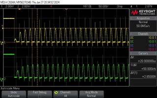
Once a Burst/Listen command is sent to the driver (Preset 1), with a frequency of 39 kHz, the OUTA and OUTB are monitored on the oscilloscope as following:
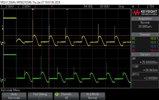
I know from this forum that OUTA and OUTB should be sinusoidal. Now from the FAQ document, it is said to reach for example a peak to peak voltage of 150 Vpp, 5V should be connected to the center tap of the transformer.
Now the output from the transformer during burst is a sinusoidal wave of 18 Vpp and 39 kHz:
![]()
The frequency of this burst is as expected, but the Vpp is not. Is there something in the configuration that I need to adjust to have the same signal but amplified to 150 Vpp?
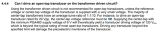
Also I tried to connect a transducer (CUSA-TR80) which has a maximum Vpp of 80 and a resonant frequency of 39 kHz, and OUTA and OUTB changed to the following:
And the output of the transformer is:
![]()
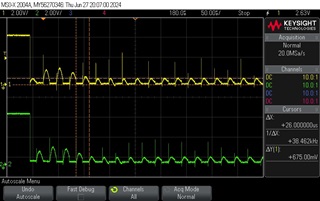
At first, I thought it was due to the fact that they included an operating frequency in the transformer datasheet (50 kHz), so I incremented the frequency to 50 kHz (0x64) and the amplitude increased on OUTA and OUTB:
And the transformer output became around 44 Vpp.
![]()
From what I understood in the datasheet, the output of the transformer must be the center tap voltage multiplied by 2 and then by the turn ratio. Why I am not getting 150 Vpp on the transformer and why the peak to peak voltage is affected by the frequency that I set in the driver?

