LDC1001-Q1: CFB pin waveform

Part Number: LDC1001-Q1
Other Parts Discussed in Thread: LDC1001

Tool/software:

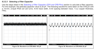
I've been trying to adjust a filter cap on an existing sensor (CFA and CFB pins).  The datasheet says to adjust the cap until the signal on the CFB pin is 1 Vp-p.  The board has air coil, and the existing filter cap is 15pF.  The problem is that I see no signal on the CFB pin.  When I probe with respect to GND, I only see noise.  When I probe with a differential probe from CFA to CFB, I can see a tiny signal that is the same frequency as on the coil, but only tens of millivolts in amplitude.  I dropped the filter cap value to 5pF, but the signal didn't get any larger.  Should I reference my measurement to GND or CFA?  What frequency should the signal on CFB be?  Should it be the same frequency that is on the coil?

  • Hello, 

    An example of the CFB waveform can be found in section 8.2.2.3 of the datasheet. 

    You should be measuring CFB with respect to GND but an oscilloscope probe can also couple to the CFB pin and throw off the measurement. To avoid this, we recommend using an active probe or decoupling your oscilloscope probe with a 1kOhm series resistor between the probe and the CFB pin. The resistor may slightly alter the amplitude of the waveform on the oscilloscope so please keep that in mind if using that approach. 

    Best Regards, 
    Justin Beigel

  • I tried all of that, but still see no waveform on the CFB pin.  There is a signal of about 4V going to the coil though.  Should the signal on the CFB pin be the same frequency as the coil?  The board originally had a 15pF filter cap from CFA to CFB.  For a test, I lowered it to 5pF.  I saw no signal with either cap.  Any suggestions?

  • Hello, 

    A 4V peak signal on the coil is normal. The CFB won't be the same frequency as the sensor coil oscillation. Here is a comparison of the two signals together: 

    I have a few follow up questions to help figure out the issue you are having: 

    • Is this happening on multiple boards or just one? 
    • Is your sensor oscillation still performing normally? 
      • Would you be able to share an oscilloscope capture of it? 
    • Can you share your schematic/layout for the LDC1001 in your application? 

    Best Regards, 

    Justin Beigel

  • The plot shows the INA signal in blue and the CFB signal in red.  The CFB signal uses the secondary voltage scale on the right.  It's only getting up to about 20mV.  This is happening on multiple boards.  They are reading inductance ok, but we'd like to improve the accuracy.  I can send you the LDC1001 portion of the schematic and layout, but I'd rather not put it somewhere that everybody can see it.  Can you send me an email address to send it to?

  • Hello, 

    Can you zoom the plot out to see multiple cycles of the LC tank oscillation. For the schematic and layout, I have sent you a friend request on this platform. Once you accept it, you can send the files directly to me in a private message. 

    Best Regards, 

    Justin Beigel