This thread has been locked.
If you have a related question, please click the "Ask a related question" button in the top right corner. The newly created question will be automatically linked to this question.
Tool/software:
Hello,
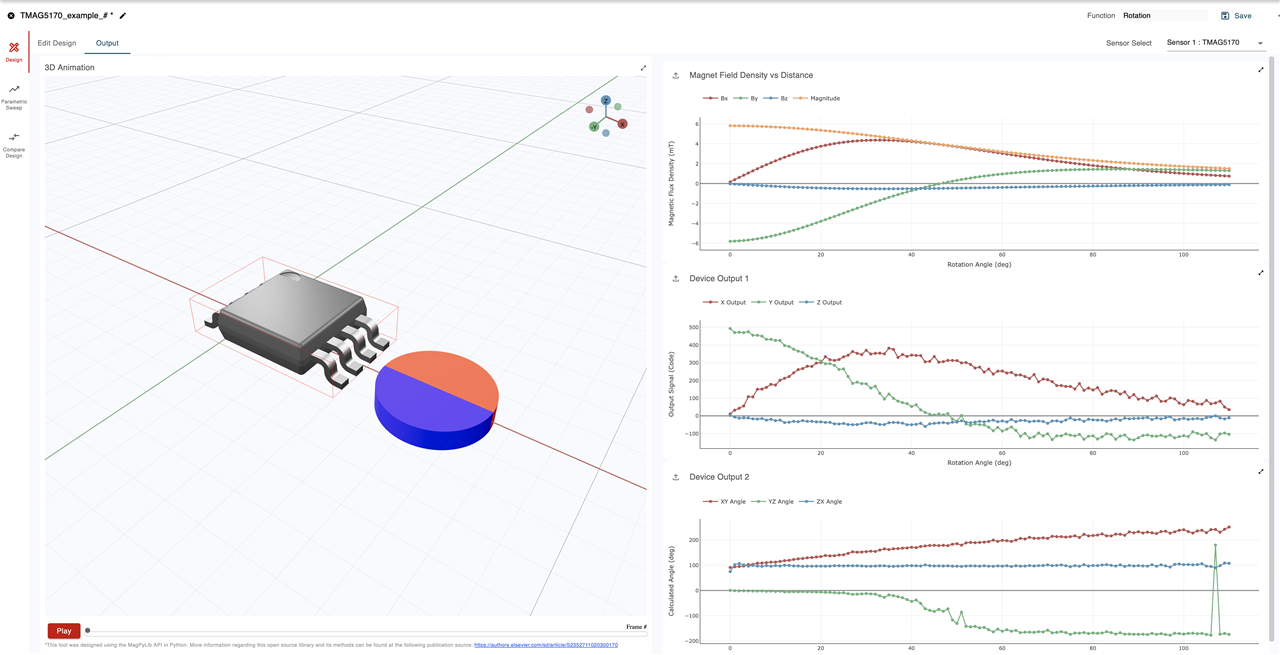
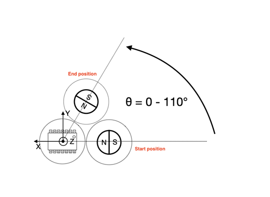
I'm looking to use this sensor for off-axis measurement and I'm planning to use cylindrical magnet (radial flux) NdFeB, Br = 1320mT, 3x0.6mm.
I see that the sensor saturates at +/-300mT so I need to know how far from the sensor I need to put the magnet? Do you have any tool that helps calculating this?
Thanks,
Milos
Hi Milos,
Thanks for posting to the Sensors forum and welcome to E2E.
We do have a tool to help with this--our online magnetic simulation tool, TI Magnetic Sense Simulator (TIMSS). You can access TIMSS here: https://webench.ti.com/timss/
You can start a new design by clicking "Create new design", then select the desired function and magnet shape (for you I think this would be "Rotation" and "Diametric cylinder", then select the sensor (TMAG5170). In this design, the magnet will rotate around the Z axis.
Under the "Magnet" tab you can set the magnet specifications, shape, and motion. Under the sensor tab you can configure the sensor specifications and placement. Note that the TMAG5170 has two variants (A1 and A2) that offer different configurable magnetic ranges (25, 50, 100mT and 75, 150, 300mT).
You can name and save your simulation and export the input parameters or simulation results.
I've attached an example simulation setup with the TMAG5170A1 in an on axis orientation with the magnet parameters you shared. You can create your own design or start from the example. To import the example, simply click "Import design file" and select the .json file.
{ "version": "3.1.3", "design_name": "TMAG5170_example", "magnet_id": 2, "poles": 2, "material_id": 7, "remanence": 1320, "temperature": 20, "temperature_coefficient": -0.12, "coercivity": 10.9, "function_id": 4, "magnet_geometry": { "outer_diameter": 3, "height": 0.6 }, "magnet_position": { "x_position": 0, "y_position": 0, "z_position": 0 }, "magnet_angle": { "x_angle": 0, "y_angle": 0, "z_angle": 0 }, "magnet_movement": { "arc_length": 360 }, "sim_setting": { "angular_step_size": 1 }, "sensor": [ { "sensor_id": "TMAG5170", "sensor_position": { "x_position": 0, "y_position": 0, "z_position": -5 }, "sensor_angle": { "x_angle": 0, "y_angle": 0, "z_angle": 0 }, "custom_inputs": { "variant": "TMAG5170A1QDGKR", "applied_vcc": 3.3, "temperature_compensation": 0, "averaging": 1, "maximum_input": 25 }, "id": -1 } ] }
Hope this helps and please let me know if you have additional questions.
Best regards,
Jesse
Hi Jesse,
Thank you for your response. In my case the magnet not only spins around its z axis but it also moves in the x,y plane. Please see the image attached.
Is there a way to model this behavior in your tool?
Best,
Milos
Hey Milos,
Yes, this will also work with the "Rotation" function. If you offset the magnet from the global Z axis by moving its initial position in the XY plane, the magnet itself still rotates around the global Z axis (as opposed to its own Z axis), which would create the type of motion shown in your image. You can center the sensor at the origin.
Best regards,
Jesse
Thanks Jesse, this helped! I managed to run the simulation but I'm not sure if I fully understand the results that the tool is showing.
1) On the first graph I see that the B that the sensor sees is super small ~6m, even the smallest sensitivity of the sensor (+/-25mT) can't pick this up. Am I reading this well?
2) Can you please tell me what is Output Signal (Code) on the second graph?
3) Calculated angle seems to be off, the magnet is rotating from 0 to 110deg, am I missing something here?
Thank you!
Best,
Milos
Hey Milos,
1) On the first graph I see that the B that the sensor sees is super small ~6m, even the smallest sensitivity of the sensor (+/-25mT) can't pick this up. Am I reading this well?
For magnetic range selection, typically you want to select the magnetic range based on the highest possible magnetic field seen by the sensor, which in this case would be ±25mT range due to the ~6mT peak you are seeing. The closer you can get to the full magnetic range without exceeding it the better. That being said, the device is capable of sensing 6mT, as shown by the corresponding output signal code in the second graph.
2) Can you please tell me what is Output Signal (Code) on the second graph?
The output signal code refers to the corresponding value stored in the X, Y, Z sensor data registers (X_CH_RESULT, Y_CH_RESULT, Z_CH_RESULT) as a result of the magnetic field strengths shown in the first graph. TIMSS takes into account input referred noise, which is why you see noise in the second and third graphs. Averaging can help to reduce the impact of input referred noise when enabled, and is taken into account in TIMSS under the "Sensor Specifications" tab.
3) Calculated angle seems to be off, the magnet is rotating from 0 to 110deg, am I missing something here?
For calculated angle you would specifically want to look at for this simulation is the XY angle. It looks like the XY angle on the third graph ranges from ~100deg to ~220deg, so a rotation range of ~120deg. Amplitude mismatch, phase shift, and noise between the X and Y magnetic field waveforms can all lead to error in the XY angle calculation with an off axis/in plane angle measurement. The two app notes below provide additional information about angle measurements using Hall-effect sensors, and provide some methods for reducing error.
Best regards,
Jesse