This thread has been locked.

If you have a related question, please click the "Ask a related question" button in the top right corner. The newly created question will be automatically linked to this question.

AWR1843BOOST: Failed to use ubuntu to run the ROS2 driver following the user's guide.

Part Number: AWR1843BOOST
Other Parts Discussed in Thread: AWR1843

Tool/software:

Hi Experts,


When I tried to use ubuntu to run the ROS2 driver following the user's guide, it failed. I guess the reason is that there is a problem with the path of my rviz_launch file being changed to the path of the configuration file. Can you tell me how to change it?


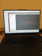
After I reinstalled the virtual machine and switched to ROS1, the point cloud displayed well. However, we want to use AWR1843boost to measure the movement of human joints, so the measurement range is about 1.5m. Can you tell me how to reduce the xy axis of this coordinate (for example, from 10m to 1.5m). Also, how to change the configuration file to make the joint movement more obvious, is it to change the resolution and radial velocity? Finally, can you provide me with a post on how to export the data in rviz? Thank you very much!

Regards,

Josel

  • Hello Josel,

    Those errors are definitely based on a bad launch file. Is there any reason you are not using one of the default launch configs that is within the ros2 driver folder itself? It would be "1843_Standard.py". RVIZ guides exist all over online and this forum is for mmWave Radar specific discussion, thus I will let you do research. I will say you will need to edit the parameters within rviz.rviz which is also in the launch folder. For an increase in resolution, you will need to change chirp parameters which can be done with the assistance of the mmWaveSensingEstimator. You can go to the advanced tab, copy and paste the contents of a cfg then do auto-populate. You will see the resulting radar performance which can then be tuned.

    Best Regards,

    Pedrhom

  • Hi Pedrhom,

    Thanks for your help. I have been able to generate the point cloud of AWR1843 through ROS1, but I still can't narrow down my detection range through the website you gave me (https://dev.ti.com/gallery/view/mmwave/mmWaveSensingEstimator/ver/2.4.0/). I mean the website is good for generating code by inputting configuration, but after I changed the configuration, the point cloud did not show up. Can you tell me which parameters to change? The following is my Xwr1843 configuration file. I want to narrow my detection range to 1 to 1.5 meters. 

    % ***************************************************************
    % Created for SDK ver:03.03
    % Created using Visualizer ver:3.3.0.0
    % Frequency:77
    % Platform:xWR18xx
    % Scene Classifier:best_range_res
    % Azimuth Resolution(deg):15 + Elevation
    % Range Resolution(m):0.044
    % Maximum unambiguous Range(m):9.02
    % Maximum Radial Velocity(m/s):1
    % Radial velocity resolution(m/s):0.13
    % Frame Duration(msec):100
    % Range Detection Threshold (dB):15
    % Doppler Detection Threshold (dB):15
    % Range Peak Grouping:enabled
    % Doppler Peak Grouping:enabled
    % Static clutter removal:disabled
    % Angle of Arrival FoV: Full FoV
    % Range FoV: Full FoV
    % Doppler FoV: Full FoV
    % ***************************************************************
    sensorStop
    flushCfg
    dfeDataOutputMode 1
    channelCfg 15 7 0
    adcCfg 2 1
    adcbufCfg -1 0 1 1 1
    profileCfg 0 77 267 7 57.14 0 0 70 1 256 5209 0 0 30
    chirpCfg 0 0 0 0 0 0 0 1
    chirpCfg 1 1 0 0 0 0 0 4
    chirpCfg 2 2 0 0 0 0 0 2
    frameCfg 0 2 16 0 100 1 0
    lowPower 0 0
    guiMonitor -1 1 1 0 0 0 1
    cfarCfg -1 0 2 8 4 3 0 15 0
    cfarCfg -1 1 0 4 2 3 1 15 0
    multiObjBeamForming -1 1 0.5
    clutterRemoval -1 0
    calibDcRangeSig -1 0 -5 8 256
    extendedMaxVelocity -1 0
    lvdsStreamCfg -1 0 0 0
    compRangeBiasAndRxChanPhase 0.0 1 0 1 0 1 0 1 0 1 0 1 0 1 0 1 0 1 0 1 0 1 0 1 0
    measureRangeBiasAndRxChanPhase 0 1.5 0.2
    CQRxSatMonitor 0 3 5 121 0
    CQSigImgMonitor 0 127 4
    analogMonitor 0 0
    aoaFovCfg -1 -90 90 -90 90
    cfarFovCfg -1 0 0 8.92
    cfarFovCfg -1 1 -1 1.00
    calibData 0 0 0

    sensorStart 
    Best regards,

    Josel
  • Hello Josel,

    Most of what you will be changing for maximizing range resolution and reducing max range is profileCfg. If the sensor doesn't start after sending an updated config, then it is due to timing issues of the chirp design. Maximizing range resolution and minimizing max range can be adjusted with increasing frequency slope and lowering digoutsamplerate. You can get some help with what parameters change what via hovering your mouse and checking the tooltip.

    Best Regards,

    Pedrhom

  • Hi Pedrhom,

    Yeah, I understand I have to change the  profileCfg. But when I changed it using advanced design's configuration, the Rviz still showed no image. After calculation, I believe that under this configuration, your frame period (120 ms) is sufficient to accommodate all Chirps (about 4.816 ms is needed). So where is the problem? Is it that the AWR1843boost hardware does not support it?


    Best regards,

    Josel
  • Hello Josel,

    Frankly I do not know who made that the default configuration for 1843 as that was before my time (1843 is over 7 years old now), but there a few weird parameters. Like idle time of 267 and dig out sample rate of exactly 5209. It is a bit odd, and since the values are all over the place in my opinion it would be hard for me to pinpoint what exactly is causing the chirp design to be unstable. I will 100% assure you this is not a device issue, but rather just the full chirp design equation not adding up

    That said, this 1843 configuration attached I approve of much more and should be a much more stable baseline configuration to start with. You will especially notice the values of profileCfg are much less "random".

    3386.profile_3d.cfg

    Best Regards,

    Pedrhom