This thread has been locked.

If you have a related question, please click the "Ask a related question" button in the top right corner. The newly created question will be automatically linked to this question.

AWR2944EVM: CAN data reception error

Part Number: AWR2944EVM
Other Parts Discussed in Thread: AWR2944

Tool/software:

Hello Team,

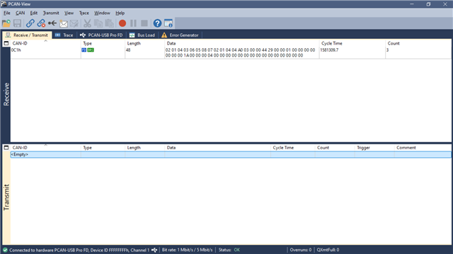
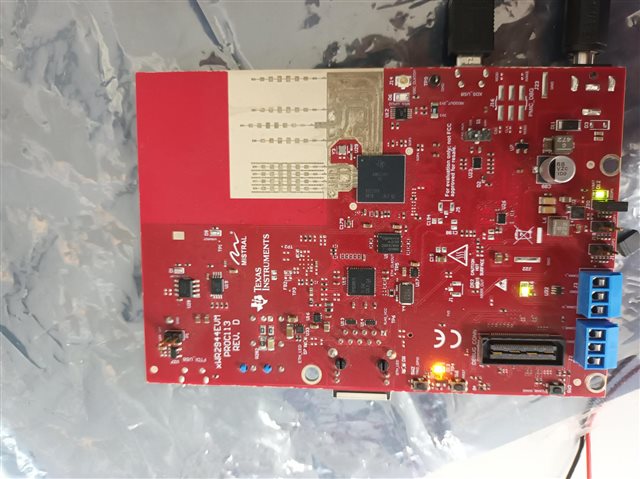
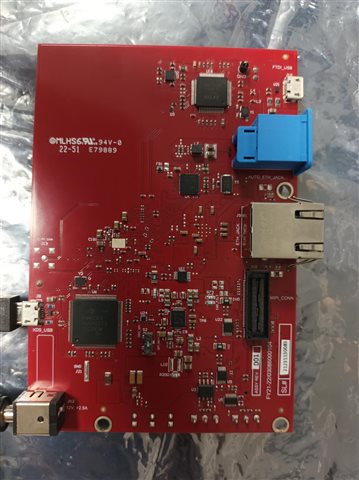
I am trying to run the awr2944_oob_object_data_over_can_DDM demo using pre-built binaries in-name of awr2944_oob_object_data_over_can_DDM.appimage and ran the Automotive visulizer for sending CLI, where there is no data received from CAN port even I have checked with Picoscope for peak check even in that there is no data coming, please can you help me out on this why data is not coming even though i follow all those steps you mentioned.

Regards,
Eswaramoorthy Sugavanam

  • Hi Eswaramoorthy,

    Object data is transmitted using MCAN-A. Can you please check if you are using CAN-A or CAN-B while testing? Also check if you are connecting CAN low and CAN high lines correctly? If it still failing, can you please rebuild the demo, run it using CCS and halt the cores to check if there is any error?

    Regards,

    Samhitha

  • Hi Samhitha,

    Sorry for late reply, been out of office for a while,

    I have re-flashed the EVM with awr2944_ccsdebug.appimage and tried to load awr2944_oob_object_data_over_can_mssDDM.xer5f for R5_0 and awr2944_oob_object_data_over_can_dssDDM.xe66 for c66 during the load-up a error arises,

     [Cortex_R5_0] **********************************************
    Debug: Launching the MMW Demo on MSS
    **********************************************
    Debug: Launched the Initialization Task
    ASSERT: 0.56079s: ../mss/mcan_transceiver.c:BoardDiag_mcanConfigSTB:211: FALSE failed !!!

    At which I have connected to CANA even though this error arises what can we do to rectify this error, I want to see data through put from the Automotive visulizer or scope in which code is a default import no even a single line or word is changed.

    And I have tested the connection both CAN high to high and CAN high to low but no data coming out even in flashed with awr2944_oob_object_data_over_can_DDM.appimage.

    Regards,
    Eswaramoorthy Sugavanam

  • Hi Eswaramoorthy,

    I have come across old E2E of yours where you have faced similar issue - AWR2944EVM: MCAN external loopback interrupt error - Sensors forum - Sensors - TI E2E support forums. The example that you were referring in the old thread and the demo that you are currently running uses same logic. Can you verify if you are able to run the external loopback example? 

    Regards,

    Samhitha

  • Hi Samhitha,

    I have done that thread long back and those error still been arising that why I closed the thread, so can you send me a procedure doc path for CAN-FD. where it runs without any error. using awr2944_oob_object_data_over_can_DDM.appimage.

    Regards,
    Eswaramoorthy Sugavanam

  • Hi Eswaramoorthy,

    I have tested the same demo at my end but I don't see any error. Are you using AWR2944 Rev D EVM?

    I will check with the team about this issue. In the meantime can you test with another EVM?

    Regards,

    Samhitha

  • Hi Samhitha,

    Yes, I am using Rev D EVM only, also I have another EVM which is tested and gives the same error that's why I was wondering if switch setting causes any error as per my EVM switch S1 is in XDS mode and S2 is in DBG_SPI mode should I have to change any of these setting.

    Regards,
    Eswaramoorthy Sugavanam

  • Hi Eswaramoorthy,

    S2 should be set to PMIC_SPI. Can you change the switch settings and test?

    Regards,

    Samhitha

  • Hi Samhitha,

    Okey let me change and give you a update,

    Regards,
    Eswaramoorthy Sugavanam

  • Hi Samhitha,

    Thank you Now I am able to see detection in scope but for parsing and seeing data in readable formate is there any procedure. I am the module below

    but the can is not recognizable by the Automotive visulizer. 

    Regards,
    Eswaramoorthy Sugavanam

  • Hi Eswaramoorthy,

    In the Automotive visualizer, it detects a PCAN dongle. I am not sure if it detects other CAN modules. Did you use any tool to see the data transmitted over CAN? 

    Regards,

    Samhitha

  • Hi Samhitha,

    Yeah I have checked with oscilloscope in which I am able to see 300mV during standby and 2.4V during setOn or data transimitte state, If the PCAN dongle can be detected by automotive visualizer then can you suggest a module with specification it would be helpfull and I can close this form.

    Regards,
    Eswaramoorthy Sugavanam 

  • Hi Samhitha,

    Now we're able to see the dc by is there is a way for verifying whether the CAN bus send any data or just Bus is on active state, with the pre-built binary what I have taken from resources explorer have making the BUS active, You have told me that you have a operational code which sends data can you please send the code and appimage .

    Regards,
    Eswaramoorthy Sugavanam

  • Hi Eswaramoorthy,

    If the PCAN dongle can be detected by automotive visualizer then can you suggest a module with specification it would be helpfull and I can close this form.

    This is the dongle that I am currently using - PCAN-USB FD: PEAK-System.

    Now we're able to see the dc by is there is a way for verifying whether the CAN bus send any data or just Bus is on active state, with the pre-built binary what I have taken from resources explorer have making the BUS active, You have told me that you have a operational code which sends data can you please send the code and appimage .

    I have used the same prebuilt binary from the Radar Toolbox that you are testing with. Did you send the CLI configuration?

    This is the data that is transmitted over CAN. I have used PCAN-View to see the data that is transmitted.

    Regards,

    Samhitha

  • Hi Samhitha,

    Currently I dont have a Peak CAN module but I have flashed and send the CLI commands which is in path:
    "C:\ti\radar_toolbox_2_20_00_05\source\ti\examples\2944_OOB_object_data_over_CAN\chirp_config\ddm_awr2944\profile_advanced_subframe_DDMA_awr2944.cfg"

    using UART itself and tried to see the data via scope but the level seems to be not change as per the tcan documentation, if the CLI has to be send only via CAN for CAN to wake up is this the case.

    Regards,
    Eswaramoorthy Sugavanam

  • Hi Eswaramoorthy,

    Configuration is sent through UART (Application port) and object data is transmitted over CAN. Can you please check and configure the following bitrate?

    Does USB-CAN analyzer support CAN-FD specifications?

    Regards,

    Samhitha

  • Hi Samhitha,

    Yes it is usable for both CAN and CAN-FD but in PCAN view it is not detected.

    Regards,
    Eswaramoorthy Sugavanam

  • Hi Eswara,

    You might not be able to use PCAN-view here since it supports a specific hardware, the USB to CAN analyzer that you are using should have a different software or tool which you can use to configure the nominal bitrate, data bitrate, frequency etc. the above screenshot that Samhitha has shared that is just for your reference.

    Can you share your CAN hardware details visible in your device manager. you will have the following details there  

    Also, you have mentioned that the USB to CAN analyzer that you are using supports the CAN and CAN-FD both, have you verified anytime that the CAN-FD is also supported?  I did check the specification of the hardware that you are using, I could not find any documentation or specifications anywhere that it supports CAN-FD. Can you share any reference document of the hardware that you are using where they have mentioned about CAN-FD.

    In our demo and visualizer at present only CAN-FD is supported, so it would be better if we can confirm whether the analyzer supports CAN-FD or not.


    Regards,

    Shruti

  • Hi Shruti,

    Sorry for the mis-conclusion it seems it only supports CAN only let me get a CAN-FD supported hardware, and thank you and sanhitha for the quick responses. let me close this thread.

    Regards,
    Eswaramoorthy Sugavanam 

  • Hi Eswara,

    Please find the hardware details below - 


    make sure that there is no bus error during the communication.

    Regards,

    Shruti

  • Hi Shruti,

    Thank you for the connection photos and I have used the same connection too.

    We have tried with the CAN-FD using pre-built binary and got a error after send cli through teraterm, I have also tried to run the demo with ccs but error remains, can you please check on this.


    after connecting to CAN-FD I am able to see some data pack but after that the above error came


    Regards,
    Eswaramoorthy Sugavanam

  • Hi Eswara,

    Can you share the screenshot of your setup?

    Regards,

    Shruti

  • Hi Shruti,

    Now I have not connected to CAN-FD send cli through teraterm


    Does anything has to be changed in setup.

    Regards,
    Eswaramoorthy Sugavanam

  • What every attached before the above thread was tested with connecting CAN-FD in the distributor office so I dont have a CAN-FD for now to show you the previous connection.

    Regards,
    Eswaramoorthy Sugavanam

  • Hi Eswara,

    As per error log, issue happens around this line in the code

    That means last frame object data is not streamed out over CANFD within single frame duration and next object data arrived. It could be due to CNAFD capture is not proper on PC side.

    Ideally default application and configuration should work as it worked at Shuri's end during virtual demo.

    Anyways, for quick debug, can your increase the frame periodicity in the CLI command (frameCfg) and re-run the application.

    6th parameter for frameCfg  CLI command in *.cfg file.

    .

    Thanks,

    Jitendra

  • Hi jitendra,

    I'll try the solution what you suggested but before that I have tried with different laptop which has a ccs version 12.60 and sdk 4.4.1.2 in which demo cli runs fine and above mentioned error is not arise so I'll try to do the same.

    Regards,
    Eswaramoorthy Sugavanam

  • Hi Samhitha,

    I have tried the OOB data over can project using different version of ccs for example 1220,1240,1260,1270,1271 with SDK version of 4.4.1.2 and radar toolbox version 2.20.0.5, 2.10.0.4, 2.0.0.6, 1.30.1.3 where the error remains the same, I have doubted the installation process what I have done and reset the PC and installed as per the instructions given in api_guide_awr294x, the tried the same process but error remains the same, for hardware connection, I used two different connection for checking.

    connection - 1:
    CANA_H - CANH
    CANA_L - CANL
    GND - GND

    during this connection state only, I am getting the error mentioned above. and one data packet 0C1h is received.

    connection - 2:
    CANA_H - CANL
    CANA_L - CANH
    GND - GND

    during this connection state, I don't see any of the data coming from CAN using peak view.

    I have double checked for connectivity and lose contact but there is no such thing.

    Also for switch cfg S1 - XDS mode, S2 - PMIC SPI mode

    can you please instruct us what else can be done.

    Also during checking for other e2e post someone faced same error but I didn't see how the error has been solved.
    e2e link : https://e2e.ti.com/support/sensors-group/sensors/f/sensors-forum/1369944/awr2944evm-sample-applications-not-working

    Regards,
    Eswaramoorthy Sugavanam

  • Hi,

    The same discussion is going on in the following thread.

    (+) AWR2944EVM: CCS Error - Sensors forum - Sensors - TI E2E support forums

    Hence, closing this thread here.

    Regards,

    Shruti