This thread has been locked.

If you have a related question, please click the "Ask a related question" button in the top right corner. The newly created question will be automatically linked to this question.

AWR2944EVM: CCS Error

Part Number: AWR2944EVM

Tool/software:

Hi Samhitha,

I have tried the OOB data over can project using different version of ccs for example 1220,1240,1260,1270,1271 with SDK version of 4.4.1.2 and radar toolbox version 2.20.0.5, 2.10.0.4, 2.0.0.6, 1.30.1.3 where the error remains the same, I have doubted the installation process what I have done and reset the PC and installed as per the instructions given in api_guide_awr294x, the tried the same process but error remains the same, for hardware connection, I used two different connection for checking.

connection - 1:
CANA_H - CANH
CANA_L - CANL
GND - GND

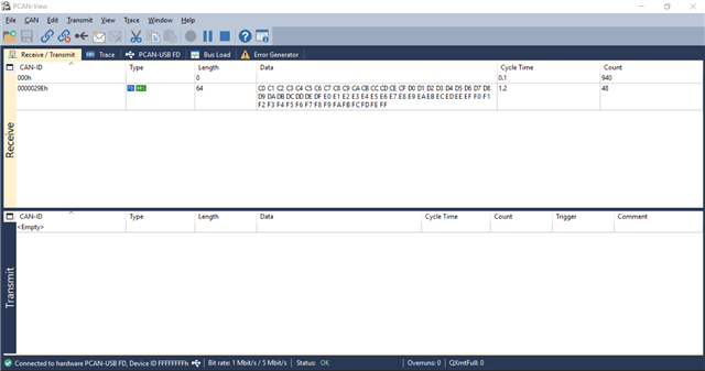
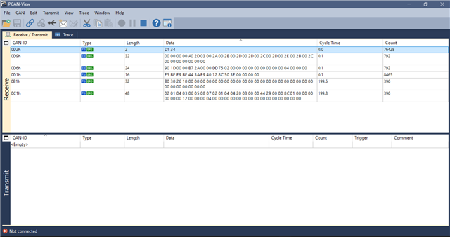
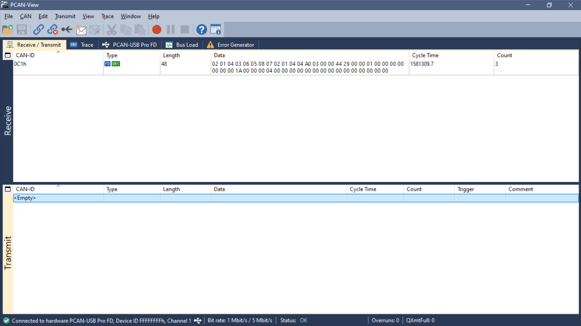
during this connection state only, I am getting the error mentioned above. and one data packet 0C1h is received.


connection - 2:
CANA_H - CANL
CANA_L - CANH
GND - GND

during this connection state, I don't see any of the data coming from CAN using peak view.

I have double checked for connectivity and lose contact but there is no such thing.

Also for switch cfg S1 - XDS mode, S2 - PMIC SPI mode

also I have tried to run the demo in ccs but error follows


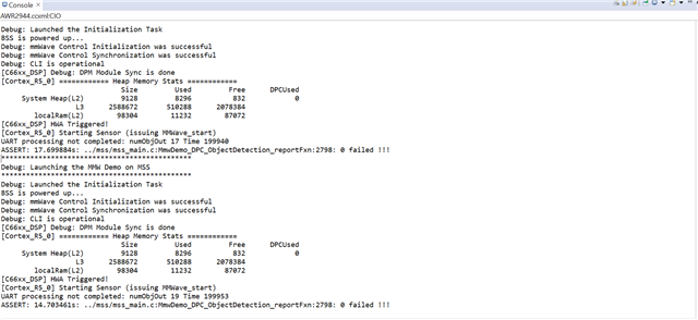
I am sending the cli without enabling heatmap only.
sensorStop
flushCfg
dfeDataOutputMode 1
channelCfg 15 15 0
adcCfg 2 0
adcbufCfg -1 1 0 0 1
lowPower 0 0
profileCfg 0 77 7 7 20.81 0 0 8.883 0 384 30000 0 0 36
chirpCfg 0 5 0 0 0 0 0 15
frameCfg 0 5 128 0 384 50 1 0
guiMonitor -1 0 0 0 0 0 0
cfarCfg -1 1 3 16 0 0 1 24.0 0 7 0 1
cfarCfg -1 0 3 16 0 0 1 15.0 0 7 0 0
compressionCfg -1 1 0 0.5 8
intfMitigCfg -1 15 18
localMaxCfg -1 6 40
antennaCalibParams 0 1 0 1 0 1 0 1 0 1 0 1 0 1 0 1 0 1 0 1 0 1 0 1 0 1 0 1 0 1 0 1
measureRangeBiasAndRxChanPhase 0 1.5 0.2
analogMonitor 0 0
calibData 0 0 0
aoaFovCfg -1 -90 90 -90 90
sensorStart

Also during checking for other e2e post someone faced same error but I didn't see how the error has been solved.
e2e link : https://e2e.ti.com/support/sensors-group/sensors/f/sensors-forum/1369944/awr2944evm-sample-applications-not-working
e2e link : AWR2944EVM: CAN output - Sensors forum - Sensors - TI E2E support forums
e2e link : AWR2944EVM: Cannot configure non-standard baud rate 3125000 in Linux Environment - Sensors forum - Sensors - TI E2E support forums

The above mentioned e2e links are the threads whose faced similar error, could you please instruct us where or what we're doing wrong.

Regards,
Eswaramoorthy Sugavanam

  • Hi ESWARAMOORTHY,

    Can you please move to the latest SDK version and try once again.

    Regards,

    Ajay

  • Hi Ajay Narayan,

    As per your suggestion, I have checked with latest version 1281 but the same error occurs.

    Regards,
    Eswaramoorthy Sugavanam

  • Hi Eswaramoorthy,

    I asked you to move to the latest SDK version, not CCS,

    Regards,

    Ajay

  • Hi Eswara,

    Can you share a screenshot of your device manager's PCAN hardware details.

    Basically, we want to check if there is any driver related issue here. We need to see the following details - 

    Check and let us know if you are getting any warning sign here in PCAN-USB FD.

    Regards,

    Shruti

  • Hi Shurti,

    I have attached the screen shot of the driver details 


    Regards,
    Eswaramoorthy Sugavanam

  • Hi Shurti,

    A quick query in the physical connection at TX and RX does the termination of 120 ohm is monitory for stable connection because during the UManual of peak system I have come across a part where is says the peak interface must be terminated with 120 Ohm either internally(peak internal termination) or external care to say does the termination should be connected.


    Regards,
    Eswaramoorthy Sugavanam
      

  • Hi Eswara,

    The CAN bus termination is important to prevent the signal distortion and data errors. in our EVM, if you check the schematic, both the CAN buses are terminated properly with 120 ohm. 

    Regards,

    Shruti

  • Hi Shruti,

    Thank you for your quick response


    but the connection photo what you shared previously does'nt has any termination connected externally in RX side, does the EVM should be connected with the 120 ohm termination part what I have shared below.
      
    Regards,
    Eswaramoorthy Sugavanam

  • Hi Eswara,

    As I said earlier, it's already there in the EVM, why do you need an extra termination? In the dongle side, I assume that internal termination should be there.

    Regards,

    Shruti

  • Hi Shruti,

    Yeah I understand either internally or external termination can be done in dongle side but as a product in delivery the internal termination is not done, So for conclusion by enabling internal termination in dongle side should be fine. and CAN will run without any error right?.


    Regards,
    Eswaramoorthy Sugavanam   

  • Hi Shurti,

    I have tried the candma_tx_with_chained_channel what you have shared with 120ohm termination on RX side, and I am able see some data after booting up but it is not continuely streaming(loop back) or is it only single data transmission


    Regards,
    Eswaramoorthy Sugavanam

  • Hi Shurti,

    In mail you said it's a 3K of data transmission at which 64B of data ran 48 time transmitte 3k of data if I am not wrong. if this works fine then what is the problem in running oob demo data over can.

    Regards,
    Eswaramoorthy Sugavanam

  • Hi Shurti,

    I have gone through the oob data over can code where, I seen that there is a struct field for changing from CAN-FD to CAN data stream and I am able to see data in PCAN-VIEW too but why is the data over CAN-FD fails is there any field is wrong in code, I have attached the code with this chat.

    void mcan_transfer(uint32_t msgIdentifier, uint8_t *data, uint32_t size, uint32_t dlc)
    {
    MCAN_TxBufElement txMsg;
    MCAN_ProtocolStatus protStatus;
    uint32_t bufNum = 0U;
    if (64U < size)
    {
    DebugP_assert(FALSE);
    }
    int32_t status = SystemP_SUCCESS;

    /* Configure Tx Msg to transmit */
    App_mcanConfigTxMsg(&txMsg, msgIdentifier, data, size, dlc);

    bufNum = 0U;
    status = MCAN_txBufTransIntrEnable(gMcanBaseAddr, bufNum, (uint32_t)TRUE);
    DebugP_assert(status == CSL_PASS);

    /* Write message to Msg RAM */
    MCAN_writeMsgRam(gMcanBaseAddr, MCAN_MEM_TYPE_BUF, bufNum, &txMsg);

    /* Add request for transmission, This function will trigger transmission */
    status = MCAN_txBufAddReq(gMcanBaseAddr, bufNum);
    DebugP_assert(status == CSL_PASS);

    /* Wait for Tx completion */
    SemaphoreP_pend(&gMcanTxDoneSem, SystemP_WAIT_FOREVER);

    MCAN_getProtocolStatus(gMcanBaseAddr, &protStatus);
    /* Checking for Tx Errors */
    if (((MCAN_ERR_CODE_NO_ERROR != protStatus.lastErrCode) ||
    (MCAN_ERR_CODE_NO_CHANGE != protStatus.lastErrCode)) &&
    ((MCAN_ERR_CODE_NO_ERROR != protStatus.dlec) ||
    (MCAN_ERR_CODE_NO_CHANGE != protStatus.dlec)) &&
    (0U != protStatus.pxe))
    {
    DebugP_assert(FALSE);
    }
    }

    static void App_mcanConfigTxMsg(MCAN_TxBufElement *txMsg, uint32_t msgIdentifier, uint8_t *data, uint32_t size, uint32_t dlc)
    {
    uint32_t i;
    /* Initialize message to transmit */
    MCAN_initTxBufElement(txMsg);
    /* Standard message identifier 11 bit, stored into ID[28-18] */
    txMsg->id = ((msgIdentifier & MCAN_STD_ID_MASK) << MCAN_STD_ID_SHIFT);
    txMsg->dlc = dlc; /* Payload size is 64 bytes */
    txMsg->fdf = TRUE; /* CAN FD Frame Format */
    txMsg->xtd = FALSE; /* Extended id not configured */
    for (i = 0U; i < size; i++)
    {
    txMsg->data[i] = data[i];
    }

    return;
    }

    typedef struct
    {
    uint32_t id;
    /**< Identifier */
    uint32_t rtr;
    /**< Remote Transmission Request
    * 0 = Transmit data frame
    * 1 = Transmit remote frame
    */
    uint32_t xtd;
    /**< Extended Identifier
    * 0 = 11-bit standard identifier
    * 1 = 29-bit extended identifier
    */
    uint32_t esi;
    /**< Error State Indicator
    * 0 = ESI bit in CAN FD format depends only on error passive flag
    * 1 = ESI bit in CAN FD format transmitted recessive
    */
    uint32_t dlc;
    /**< Data Length Code
    * 0-8 = CAN + CAN FD: transmit frame has 0-8 data bytes
    * 9-15 = CAN: transmit frame has 8 data bytes
    * 9-15 = CAN FD: transmit frame has 12/16/20/24/32/48/64 data bytes
    */
    uint32_t brs;
    /**< Bit Rat Switching
    * 0 = CAN FD frames transmitted without bit rate switching
    * 1 = CAN FD frames transmitted with bit rate switching
    */
    uint32_t fdf;
    /**< FD Format
    * 0 = Frame transmitted in Classic CAN format
    * 1 = Frame transmitted in CAN FD format
    */
    uint32_t efc;
    /**< Event FIFO Control
    * 0 = Don't store Tx events
    * 1 = Store Tx events
    */
    uint32_t mm;
    /**< Message Marker */
    uint8_t data[MCAN_MAX_PAYLOAD_BYTES];
    /**< Data bytes.
    * Only first dlc number of bytes are valid.
    */
    }MCAN_TxBufElement;

    can you say if any of the field is not right that I can correct.

    Regards,
    Eswaramoorthy Sugavanam

  • Hi Eswara,

    Are you saying that if you change the CAN mode in the demo from FD to classic then you are seeing the data in PCAN?

    Can you load both the codes in ccs, i.e. example and the demo and compare the configuration values? mainly check the MSS_MCANA_CFG:CCCR register values, since the CAN dma example is working as expected for you. Ideally you should set the mode to FD since with classic CAN we can only send a limited size of data.

    Also, have you tried running the default CAN OOB demo with the RX side termination? did you get any data in Peak view with this case?

    Regards,

    Shruti

  • Hi Shruti,

    Actually in CAN-FD configuration, I have also tried to see at what spec the MCAN transmitting data in syscfg and found that they're not matching because the nom and data bitrates are not matching with actually spec in code where If I change the sampling point in Nom and data bitrate from 75% to 85% and 87.5, I am able to see continues transmission can you check it once if the syscfg matches in your side. and how to change to 75% sampling point in which you have shown the demo.


    Regards,
    Eswaramoorthy Sugavanam

  • Hi Eswara,

    Can you share the snapshot of syscfg which you are referring to here?  Also, share the snapshot of that part of the code where you are telling that the configuration is not matching.

    Regards,

    Shruti

  • Hi Shurti,

    Sorry for wrong info only in syscfg and in Automotive visulizer code, I have seen the different setting I'll attached the screen shot of syscfg and pcan connect setting what I have used.

    Syscfg setting.


    And PCan-View setting 


    Automotive visulizer code 


    At the current setting, I am able to see received data in PCAN-view but I am not able to see and data point during running the automotive visulizier can you explain what setting in syscfg and automotive visulizer are different from what cfg you have shared.


    And what is the supported syscfg and pcan-view setting for running in both automotive visulizer and pcan-view.


  • Hi Eswara,

    So now with the sample point modification, you can see the demo data in PCAN view software while running the demo, but not able to plot that in visualizer. Is that correct?

    Can you do the following experiment- 

    In the demo mss_main.c file modify the timing configuration, consider the frequency as 80Mhz and modify the following parameter for 1Mhz nominal and 5Mhz data bit rate.

    you can compare these parameters with the test example which I shared previously for reference. after the modification, rebuild the demo and try to run the same.

    If this doesn't work, then you can try modifying these parameters in the visualizer code as per the mss_main.c file.

    Let me know if it works.

    Regards,

    Shruti

  • Hi Shruti,

    I'll try that out but I am bit confused you said the cfg in sampling point are 75% for both nom and data bitrate but how come code from resource explore has 85.

    Regards,
    Eswaramoorthy Sugavanam

  • Hi Eswara,

    You can use the sample point as 85 and 87.5 for the demo. For the visualizer, I would suggest you to modify the CAN parameter in the visualizer code as per the demo syscfg default settings.

    Regards,

    Shruti

  • Hi Shruti,

    Okey, I'll try it out.

    Regards,
    Eswaramoorthy Sugavanam

  • Hi Shruti,

    I have made changes in visualizer for specific and got data plotting in visualizer.

    Regards,
    Eswaramoorthy Sugavanam   

  • Hi Eswara,

    Good to know that your issue is resolved.

    Closing this thread here.

    Regards,

    Shruti