AWR2944EVM: Cannot configure non-standard baud rate 3125000 in Linux Environment

Part Number: AWR2944EVM
Other Parts Discussed in Thread: AWR2944

Hi,

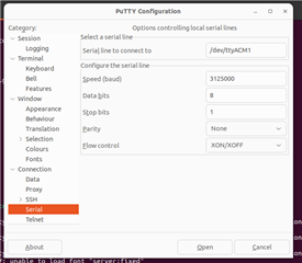
We are not able to set non-standard baud rate 3125000 used in AWR2944 "High End Corner Radar" Lab example to read serial data in Linux. However, We are able to set it in Windows environment.

$ stty -F /dev/ttyACM1 3125000 // do not work with customized baud rate
stty: invalid argument ‘3125000’


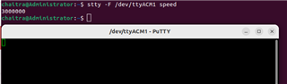
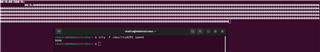
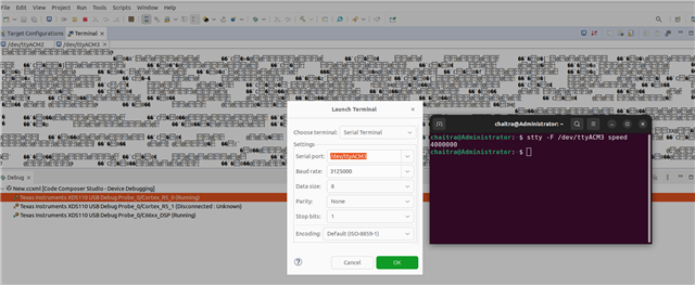
$ stty -F /dev/ttyACM1 speed // Able to set standard baud rate
3500000

We need to read the serial data using AWR2944 in Linux. So, do you have a working tutorial/example that shows how this non standard baud rate can be enabled in Linux environment?

Thanks

  • Hi Chaitra,

    You can use PuTTY tool to connect to the serial port with custom baud rate.

    Thanks,
    Anirban

  • Hi Anirban,

    Thanks for the reply!

    Using putty tool, even though we set the custom baud rate, it will get set to the nearest standard baud rate.

    Setting the baud rate to 3125000

    But it got set to 3000000

    We have tried with other tools and library functions (minicom, boost, ioctl APIs ). But did not succeed in setting this custom baud rate.

    Thanks,

    Chaitra

  • Hi Chaitra,

    I think screen tool should work with the following command : sudo screen /dev/ttyACM1 3125000

    I tried with this command, it worked for me.

    Thanks,
    Anirban

  • Hi Anirban,

    This command "sudo screen /dev/ttyACM1 3125000" will open the serial port but with a default baud rate of 9600. The data gets corrupted unless we set it to 3125000.

    Is there any test results available for the serial data performed on "High end corner Radar" lab example in linux ?

  • Hi Chaitra,

    I'm sorry, we don't have a test result right now to run HECR and collect serial data in Linux environment.

    But, here is what you can do at your end to get the desired serial data - 

    • Install CCS on your Linux environment [Download Link]
    • Connect the device and open Target Configuration in CCS (View Tab > Target Configurations)
    • Create a Target Configuration for AWR2944 and launch the target configuration
    • Connect to both the cores R5F and C66x
    • Do CPU Reset for both and Load the Demo binaries respectively 
    • Run R5 and then run C66 cores
    • Now, go to View tab > Click on Terminal 
    • In the terminal window press Ctrl+Alt+Shift+T
    • In launch terminal window choose your UART COM Port and baud rate i.e. 115200
    • Press the same combo again and choose your Serial DATA Port and custom baud rate i.e. 3125000
    • In the UART terminal put you configurations line by line
    • After sensor start successfully check DATA Port for Serial Data 

    .

    Thanks,
    Anirban

  • Hi Anirban,

    Here also I ended up with same result. The serial port is opening but with a standard baud rate of 4000000 not with what I set in the terminal (3125000).

    Is it possible to check with the developers of "HECR lab" example whether serial data is retrieved correctly in Linux with this custom baud rate ?


    However, in windows we are able to set this baud rate(3125000) exactly and retrieve all the detection and tracker data correctly.
    But in Linux with the nearest standard baud rate 3500000 we are able to get the data but it is corrupted slightly.

    Thanks,

    Chaitra

  • Hey Chaitra,

    .

    I think HECR Lab example is not the blocker here. At my end I faced same kind of issue too and tried stackoverflow, but the situation there is also same. People are struggling to set custom baud rate in Linux environment. This might be a limitation of Linux environment.  

    I'd suggest you to proceed with windows environment for now if OS is not a blocker for you use case.

    .

    Thanks,
    Anirban

  • Hi Anirban,

    Yes. I agree. Its an issue with Linux kernel to set custom baud rates. But we have limitation in using windows for our use case.

    So, I was just curious if the lab example was already tested on Linux for this particular scenario. Otherwise, we may have to look for other options.

    Thanks,

    Chaitra

  • Hi Chaitra,

    Can you try the below changes -

    * Try changing MMWDEMO_DATAUART_MAX_BAUDRATE_SUPPORTED macro value in (/demo/mss/)mmw_cli.h to nearest standard baud rate

    * In mss.syscfg, change the baud rate of CONFIG_UART1 to nearest standard baud rate

    Let me know your observations on this.

    Thanks,
    Anirban

  • Hi Anirban,

    I have tested with above changes. Here is my observation:


    Data from Radar is corrupted with the above changes.

    Both in windows and ubuntu cannot retrieve data correctly.

    Nearest standard baud rate used are 3000000 and 3500000.

    Thanks,

    Chaitra

  • Hi Chaitra,

    That is not expected, although if you can try one more experiment as below - 

    If you are using OOB Demo application, you can use the configDataPort command in the cfg file you are using. It takes 2 args - new baudrate and ack req flag. You can find this command on SDK User Guide.

    Insert this additional command and try with demo application and let me know the observations

    Thanks and Regards,
    Anirban 

  • Hi Anirban,

    I tried this with both OOB demo and HECR demo. But unfortunately the data is not coming correctly for any other standard baud rates. In the stream not even able to find the magic word.


    mmwDemo:/>sensorStop                                                         
    Done                                                                         
    mmwDemo:/>configDataPort 3500000 1                                           
    Done                                                                         
    mmwDemo:/>sensorStart
    Done

    $ stty -F /dev/ttyACM1 speed
    3500000
    $ stty -F /dev/ttyACM0 speed
    115200

    Thanks,

    Chaitra

  • Hi Chaitra,

    As this issue is related to the Linux Kernel and faced by many, I think Linux forum would be the best place ask this issue.

    Thanks,
    Anirban

  • Hi Anirban,

    We will try to get the data via CAN. I hope this should work.

    Thanks for your support.

    Thanks,

    Chaitra

  • Surely, CAN doesn't have that kind of limitations. Hope this works at your end.

    You can update me here as well.

    Thanks,
    Anirban 

  • Hi Anirban,

    I am using awr2944_oob_object_data_over_can lab example to obtain CAN data.

    I have used Peak CAN adapter and reading the data using mmwave CAN visualizer.

    But I am not able to read the data after sending valid configurations.

    I did connect the target to CCS and it gives the below error:

    [Cortex_R5_0] **********************************************
    Debug: Launching the MMW Demo on MSS
    **********************************************
    Debug: Launched the Initialization Task
    BSS is powered up...
    Debug: mmWave Control Initialization was successful
    Debug: mmWave Control Synchronization was successful
    Debug: CLI is operational
    [C66xx_DSP] Debug: DPM Module Sync is done
    [Cortex_R5_0] ============ Heap Memory Stats ============
    Size Used Free DPCUsed
    System Heap(L2) 9128 8296 832 0
    L3 2588672 510288 2078384
    localRam(L2) 98304 11232 87072
    [C66xx_DSP] HWA Triggered!
    [Cortex_R5_0] Starting Sensor (issuing MMWave_start)
    UART processing not completed: numObjOut 37 Time 199974
    ASSERT: 60.678708s: ../mss/mss_main.c:MmwDemo_DPC_ObjectDetection_reportFxn:2788: 0 failed !!!

    And the sensor is stuck here forever.

    I am not sure if I am missing something!!

    Sometimes, I get the header data once and then it gets stuck with the same error.

    Thanks,

    Chaitra

  • Hi Chaitra, 

    According to the log, it seems the UART data transmission issue. 

    Can you connect to the device cores when you're facing this issue and share some screenshots of the functions call stack on each core?

    Thanks,
    Anirban

  • Hi Anirban,

    I have attached the screenshots below:


    Other observation:

    When "#define CAN_STREAM 1" macro in mss_main.c is disabled, object data over uart is coming properly without the above error.

    Thanks,

    Chaitra

  • Hi Chaitra,

    While using CAN OOB demo, you are connecting to UART as well right?

    Regards,
    Anirban

  • Yes, I am connecting to uart as well. In order to send configurations we need uart connection also.

    Thanks,

    Chaitra

  • Chaitra, let me pass your thread to our CAN OOB demo expert.

    Regards,
    Anirban

  • Ok. Thank you.

  • Hi Chaitra,

    I have used Peak CAN adapter and reading the data using mmwave CAN visualizer.

    But I am not able to read the data after sending valid configurations.

    AWR2944 OOB Object Over CAN demo is not tested using mmwave_can_visualizer tool in the Radar Toolbox. Use PCAN-view to read the object data. In order to visualize the data, you can use Automotive Visualizer present in the Radar Toolbox. 

    Please ensure that you are using MCANA to run AWR2944 OOB Object Over CAN demo. Also make sure that transfer of heatmaps is disabled in the guimonitor command.

    Regards,

    Samhitha

  • Hi Chaitra,

    I have gone through the entire thread. Can you please try sending the 'configDataPort 3125000 1' command over Application/User UART port, the application will ack on data port with 0xFF sequence.

    mmwDemo:/>configDataPort 3500000 1                                           
    Done

    You have tried configuring the data port at a different baud rate.

    Regards,

    Samhitha

  • Hi Samhitha,

    We wanted to configure data port with standard baud rate. (3500000)

    'configDataPort 3125000 1' --> These customized baud rates cannot be set in Linux.


    Thanks,

    Chaitra

  • Hi Samhitha,

    I am using these configurations in PCAN view. 
    f_clock_mhz=40, nom_brp=5, nom_tseg1=5, nom_tseg2=2, nom_sjw=1, data_brp=1, data_tseg1=4, data_tseg2=3, data_sjw=1

    I dont see any received frames in PCAN view. 

    I am uising these config from dermo eaxample:
    sensorStop
    flushCfg
    dfeDataOutputMode 1
    channelCfg 15 15 0
    adcCfg 2 0
    adcbufCfg -1 1 0 0 1
    lowPower 0 0
    profileCfg 0 77 267 7 57.14 0 0 70 1 384 13349 0 0 30
    chirpCfg 0 5 0 0 0 0 0 15
    frameCfg 0 5 16 0 384 200 1 0
    guiMonitor -1 2 0 0 0 0 0
    cfarCfg -1 1 3 16 0 0 1 24.0 0 7 0 1
    cfarCfg -1 0 3 16 0 0 1 15.0 0 7 0 1
    compressionCfg -1 1 0 0.5 8
    intfMitigCfg -1 15 18
    localMaxCfg -1 6 40
    antennaCalibParams 0 1 0 1 0 1 0 1 0 1 0 1 0 1 0 1 0 1 0 1 0 1 0 1 0 1 0 1 0 1 0 1
    measureRangeBiasAndRxChanPhase 0 1.5 0.2
    analogMonitor 0 0
    calibData 0 0 0
    aoaFovCfg -1 -90 90 -90 90
    sensorStart

    After some debugging I get to know that in mss_can.c, its not going inside below if loop.


    if (MCAN_INTR_SRC_TRANS_COMPLETE ==
    (intrStatus & MCAN_INTR_SRC_TRANS_COMPLETE))
    {
    SemaphoreP_post(&gMcanTxDoneSem);
    }

    I guess, its an issue with rate of transmission. New data is coming in queue before the previous one is transmitted completely. Could you please help me out with the proper bit rate configurations ?

    Thanks,

    Chaitra

  • Hi Chaitra,

    Try with the following configuration.

    Regards,

    Samhitha

  • Hi Samhitha,

    With this configuration also I am getting the header data and then CAN communication is lost.

    Debugging is giving same error


  • Hi Chaitra,

    Can you try running the demo using prebuilt binaries?

    Regards,

    Samhitha

  • Hi Samhitha,

    I have tried with prebuilt binaries as well. [awr2944_oob_object_data_over_can.appimage]. With this I am not getting any data over CAN.

    But in debug mode using CCS, and enabling only header, once data gets transmitted and then CAN communication stops.

    I suspect there is some conflict wrt CAN transmission time and the frame period.

    Thanks,

    Chaitra

  • Hi Chaitra,

    I have run the demo but I don't see any issue. Can you check the PCAN connections to the EVM? Also ensure that you are using CAN A. Can you test using another EVM if the issue persists?

    Regards,

    Samhitha

  • Hi Samhitha,

    I have made the PCAN connections to EVM as below. CAN-L to CANA_L, CAN-H to CANA_H and GND is shorted and connected to CANA gnd.

    I have couple of questions:

    1. Can you please send me the configuration that you used for the demo ?

    2. Do I need to use a CAN Bus circuit (as shown below) in between ?

    3. After receiving only header data once, PCAN view shows stuff error. What does this imply ?


    Thanks,

    Chaitra

  • Hi Chaitra,

    Can you please send me the configuration that you used for the demo ?

    You can use any configuration from the 2944_OOB_object_data_over_CAN demo. I have used the following configuration for testing.

    sensorStop 
    flushCfg 
    dfeDataOutputMode 1 
    channelCfg 15 15 0 
    adcCfg 2 0 
    adcbufCfg -1 1 0 0 1 
    lowPower 0 0 
    profileCfg 0 77 7 7 20.81 0 0 8.883 0 384 30000 0 0 36 
    chirpCfg 0 5 0 0 0 0 0 15 
    frameCfg 0 5 128 0 384 50 1 0 
    guiMonitor -1 0 0 0 0 0 0
    cfarCfg -1 1 3 16 0 0 1 24.0 0 7 0 1
    cfarCfg -1 0 3 16 0 0 1 15.0 0 7 0 0
    compressionCfg -1 1 0 0.5 8 
    intfMitigCfg -1 15 18
    localMaxCfg -1 6 40
    antennaCalibParams 0 1 0 1 0 1 0 1 0 1 0 1 0 1 0 1 0 1 0 1 0 1 0 1 0 1 0 1 0 1 0 1
    measureRangeBiasAndRxChanPhase 0 1.5 0.2
    analogMonitor 0 0 
    calibData 0 0 0 
    aoaFovCfg -1 -90 90 -90 90
    sensorStart

    Do I need to use a CAN Bus circuit (as shown below) in between ?

    It's not required to make any extra connections if you are using 2944EVM.

    After receiving only header data once, PCAN view shows stuff error. What does this imply ?

    I have found a thread you can refer to it - (+) LAUNCHXL-F28069M: CAN Stuff Error Message - C2000 microcontrollers forum - C2000Tm︎ microcontrollers - TI E2E support forums. Can you try running the demo on another EVM?

    Regards,

    Samhitha