This thread has been locked.

If you have a related question, please click the "Ask a related question" button in the top right corner. The newly created question will be automatically linked to this question.

IWR6843ISK: The understanding of Angle FFT when deal with raw data captured from DCA1000EVM

Part Number: IWR6843ISK
Other Parts Discussed in Thread: DCA1000EVM,

Tool/software:

Hi Team,

I have some questions about the angle estimation from the raw data.

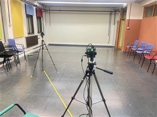
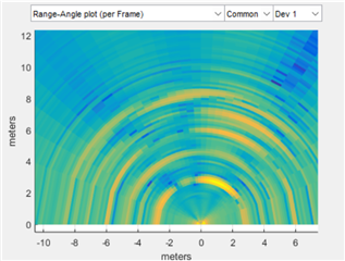
As the figure shows, I measured a corner reflector on the left hand of the radar.

Figure 1

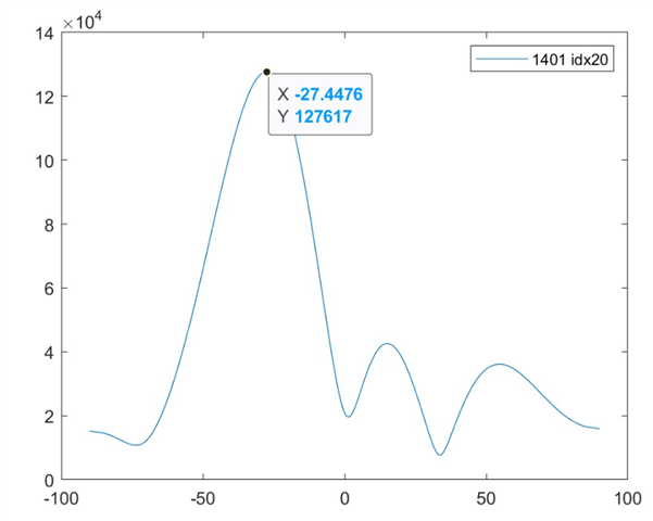
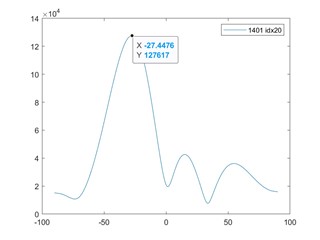
However, when I did angle FFT (513 points) on the corresponding range bin, I got the peak at the negative angle, as the figure shows.

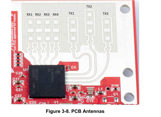
But the antenna arrangement is shown as this figure, so that means when we see the radar board from the back, the antenna layout should be RX4-RX3-RX2-RX1, which also means that I should expect the peak of the Angle FFT appears on the positive angle instead of the negative angle.


Moreover, when I observed the heatmap from the mmWave studio, we can also see that the strong reflection from the right hand side, which is contradictory to the placement of the corner reflector. And I also checked the MATLAB example, if I calculate the x,y,z coordinate, then I will get the similar thing as the mmWave Studio shows.


 if length(angleEst) > 0
for iobj = 1:length(angleEst)
    angles_all_points (iobj,1:2)=angleEst(iobj).angles(1:2);
    angles_all_points (iobj,3)=angleEst(iobj).estSNR;
    angles_all_points (iobj,4)=angleEst(iobj).rangeInd;
    angles_all_points (iobj,5)=angleEst(iobj).doppler_corr;
    angles_all_points (iobj,6)=angleEst(iobj).range;
    %switch left and right, the azimuth angle is flipped
    xyz(iobj,1) = angles_all_points (iobj,6)*sind(angles_all_points (iobj,1)*-1)*cosd(angles_all_points (iobj,2));
    xyz(iobj,2) = angles_all_points (iobj,6)*cosd(angles_all_points (iobj,1)*-1)*cosd(angles_all_points (iobj,2));
    %switch upside and down, the elevation angle is flipped
    xyz(iobj,3) = angles_all_points (iobj,6)*sind(angles_all_points (iobj,2)*-1);
    xyz(iobj,4) = angleEst(iobj).doppler_corr;
    xyz(iobj,9) = angleEst(iobj).dopplerInd_org;
    xyz(iobj,5) = angleEst(iobj).range;
    xyz(iobj,6) = angleEst(iobj).estSNR;
    xyz(iobj,7) = angleEst(iobj).doppler_corr_overlap;
    xyz(iobj,8) = angleEst(iobj).doppler_corr_FFT;
    
end


Actually I went through almost every thread regarding the same issue, for example,

https://e2e.ti.com/support/sensors-group/sensors/f/sensors-forum/926713/awr1443boost-aoa-estimation

https://e2e.ti.com/support/sensors-group/sensors/f/sensors-forum/846402/iwr6843isk-ods-my-elevation-angle-fft-result-is-upside-down

But none of them gives a concrete answer to the question regarding the reverse angles.

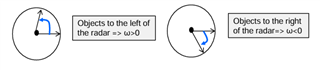
Also, I am confused about the training video about Angle FFT (www.ti.com/.../5415560018001, the graph doesn't match well with the text, when the objects to the left of the radar, the graph shows that ω is smaller than 0.

To conclude, my questions are,

How should I understand the mapping of channel 1,2,3,4 to RX1,2,3,4? 
And what is the correct way to differentiate the negative and positive angles when I am doing Angle estimation?

I am really looking forward to your response! Thanks in advance!

Best,

Bei

  • Hi

    Thanks for your query. Please allow us a couple of days to respond

    Regards

  • Hello Bei,

    Are you aware of the virtual antenna mapping of he 6843ISK? This information can be seen on the Radar Toolbox's Antenna Radiation Pattern page for the 6843ISK

    https://dev.ti.com/tirex/explore/node?node=A__AR15ErXW3EPDqIyLkpkGEw__radar_toolbox__1AslXXD__LATEST

    Best Regards,

    Pedrhom

  • Hi Pedrhom

    I am aware of this, but I thought the mapping figure is showing the mapping when we see it in front of the radar. So when we see from the back of the radar, it should be the opposite order. I believe that this is also how mmWave studio and Matlab Example deal, that is why the range-angle plot is opposite as I expected.

    Best,

    Bei

  • Hello Bei,

    Yes we do an extra calculation to do the intended data manipulation to address the antenna. You will see this across all our deliverables, especially for devices where we offer multiple antenna designs for the same chip. For example with 6843 People Counting example demo found in the Radar Toolbox in the TI Developer Zone, we have the following parameters to address the 6843ISK's antenna pattern.

    antGeometry0 0 -1 -2 -3 -2 -3 -4 -5 -4 -5 -6 -7
    antGeometry1 -1 -1 -1 -1 0 0 0 0 -1 -1 -1 -1
    antPhaseRot 1 1 1 1 1 1 1 1 1 1 1 1

    And then for 6843AOP it is setup like this

    antGeometry0 -1 -1 0 0 -3 -3 -2 -2 -1 -1 0 0
    antGeometry1 -1 0 -1 0 -3 -2 -3 -2 -3 -2 -3 -2
    antPhaseRot 1 -1 1 -1 1 -1 1 -1 1 -1 1 -1
    Best Regards,
    Pedrhom
  • Hi Pedrhom,

    To conclude, how should I deal with the data from different channels to get the correct angle estimation after collecting the raw data from IWR6843ISK DCA1000EVM? Should I reverse the sequence like mmWave studio and the Matlab example ([TX2-RX4, TX2-RX3, TX2-RX2, TX2-RX1, TX1-RX4, TX1-RX3, TX1-RX2 TX2-RX1]) do or should I just do azimuth Angle FFT like this, [TX1-RX1, TX1-RX2, TX1-RX3, TX1-RX4, TX2-RX1, TX2-RX2, TX2-RX3, TX2-RX4]? Please let me know what should I do with the data. 

    Best,

    Bei

  • Hi, Bei:

    When you calculate Azimuth angle, we can use the following 8 antennas because they share the same elevation level.  

    [TX1-RX1, TX1-RX2, TX1-RX3, TX1-RX4, TX3-RX1, TX3-RX2, TX3-RX3, TX3-RX4]

    As you mentioned, when the sensor is facing forward, they kinds of switch the order, that is why we assume the index of these 8 antennas are

    azi_ind = - [0, 1, 2, 3, 4, 5, 6, 7] 

    Note that we give a negative index for these antennas.  With this index change, you can now follow the regular formular for angle estimation. 

    steeringVec(theta) = exp(-1j*2*pi*azi_ind*d/lambda*sin(theta)

    since d = lambda/2;

    steeringVec(theta) = exp(-1j*pi*azi_ind*sin(theta));

    It will be equivalent if you program the above antenna spacing index as m_ind = [7, 6, 5, 4, 3, 2, 1, 0]

    Let me know if it makes sense to you.

    Best,

    Zigang

  • Hi Zigang,

    Thanks a lot for your reply, and it does make sense theoretically. However, I still have the problem in practice.

    As the above figures show, when I do the simple experiment as the figure shows, I am supposed to see the peak on the right if I just use the index as [0,1,2,3,4,5,6,7]. But now I can see the peak on the left. 

    In my understanding, mmWave studio also does the Angle FFT as [7, 6, 5, 4, 3, 2, 1, 0], so I expect to see the strongest area caused by the corner reflector on the left. However, from the screenshot of the mmWave studio, we observed a strong object on the right-hand side. 

    That is why I am very confused about the angle FFT part now.

    Best,
    Bei

  • Hi, Bei:

    Because mmWave studio does not know the antenne layout, we do not usually trust the studio angle results. 

    How did you get the spectrum figure in your original post?  To me, the result makes sense, i.e., the target on the left side should have a negative angle.  

    Best,

    Zigang

  • Hi Zigang,

    What I did is TDM-MIMO, and I followed the basic procedure to do pos-processing. I collected ADC Data->find the right Range FFT bin for the corner reflector -> arrange the index as [TX1-RX1, TX1-RX2, TX1-RX3, TX1-RX4, TX3-RX1, TX3-RX2, TX3-RX3, TX3-RX4] and do Angle FFT. So I ended up getting the correct angle without reserving the angle, that is why I am very confused,

    Best,

    Bei

  • Hi, Bei:

    It really depends on the detail implementation of your DOA algorithm.  How did you do angle FFT?  How do you calculate the angle after range FFT? Did you do fftshift after FFT?

    Best,

    Zigang

  • Hi Zigang,

    I did Angle FFT after range FFT, and I did fftshit after angle FFT.

    idisbin = 34;
    rangefft_temp = [rangeFFT_frame(iref, 1:1:4, idisbin), rangeFFT_frame(iref+1, 1:1:4, idisbin)]; % for 3 tx
    angefft_temp = fftshift(fft(rangefft_temp,513));


    Best,

    Bei

  • Hi, Bei:

    Your implementation is correct.  That is how you implement angle beamforming with FFT.   

    But if you follow the Bartlett beamforming approach, the steering vector is 

    steeringVec(theta) = exp(-1j*pi*azi_ind*sin(theta));

    Where you have to use the modified, i.e, azi-ind = [7, 6, 5, 4, 3, 2, 1, 0].  But then you compute your Bartlett beamforming with the formula below

    spectrum(theta)= abs(steeringVec(theta)' * x).^2;
    Where x is your received peak cross different antenna (rangeft_temp in your implementation).
    There is a conjugate above, which kind of flip the sign again.   
    Hope it is making sense to you now.  
    Best,
    Zigang
  • Hi Zigang,

    Just a quick comment, I am just using simple TDM MIMO instead of BPM MIMO or any beam forming technique. In the case of TDM-MIMO, does what you said still hold true?

    Best,

    Bei

  • Yes, it applies.  

    Best,

    Zigang