This thread has been locked.

If you have a related question, please click the "Ask a related question" button in the top right corner. The newly created question will be automatically linked to this question.

IWRL6432AOPEVM: IWRL6432AOPEVM

Part Number: IWRL6432AOPEVM
Other Parts Discussed in Thread: IWRL6432AOP, UNIFLASH, MMWAVE-L-SDK, IWRL6432, SYSCONFIG

Tool/software:

Hello friends, I have purchased the IWRL6432AOPEVM radar board. My goal is to get the data of distance, presence, motion etc. to a host MCU through UART communication and parse it . I have some questions as following:

  1. Which are the UART terminals on the Board IWRL6432AOPEVM where I can connect the Host MCU's UART pins to receive the data to the host MCU or any serial terminal to the PC ?
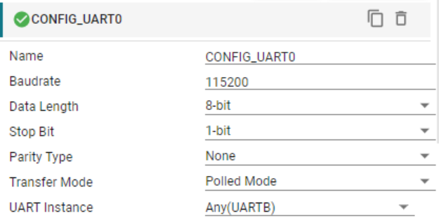
  2. What are the default configurations of the UART of IWRL6432AOPEVM in terms of Data Bits per packet, Parity and stop bits and use of RTS and CTS?
  3. Do we start getting the data on UART terminal as a continuous stream after powering the Board IWRL6432AOPEVM or is can we enable or disable it as per our choice? 
  4. How can we change the baud rate of the UART communication? Does the same baud rate is used to send the data to GUI as well?
  5. How can we control the start and stop operation of radar sensor so that we could save the power and enable the sensing only when required (usually periodic).
  6. It was mentioned in the document on this link > "software-dl.ti.com/.../MOTION_AND_PRESENCE_DETECTION_DEMO.html the frame header size is 52 bytes but after calculating the size of the frame header structure(MmwDemo_output_message_header_t) and even adding the TLV structure(MmwDemo_output_message_tl_t) size does not gets equal to 52 bytes, Is it that some data fields are not mentioned or something else is the reason?

I would be really grateful for your support.

Thank You.

  • Hello, 

    Here are some answers to your questions.

    1. After referring to the EVM schematic, there are no headers for UART transmission on the IWRL6432AOPEVM UART is only passed to the USB port of the board. So you can connect to a serial terminal of the PC using USB; as for connecting to your host MCU, it may be possible with some board modifications. I will ask a HW expert to comment on this.

    2. The default UART configuration settings are shown in the .syscfg file for the example application.

    3. By default, the out of box example application for IWRL6432AOP (motion and presence detection) requires that the configuration be sent to the device prior to any sensing and data streaming. The guiMonitor command can be used to control which outputs are enabled. This command is described in the CLI Interface section on this page.

    4. If you wish to change the initial/defualt baud rate of the communication you should modify the setting in the UART section of the .syscfg file. If you wish to update the baud rate during operation, then you can use the baudrate command. This command is described in the CLI Interface section on this page. Note, if you use the baudrate CLI command, then this baud change also needs to be comprehended by the host.

    5. If the sensor operation is periodic then you can use the frameCfg command to configure the frame periodicity and enable low power modes so that when the device completes its operation for a single frame then it enters a deep sleep mode which consumes very little power. It is also possible to enter this deep sleep and wakeup upon interrupt from the host (power driver example).

    6. 52 bytes may be a typo in the documentation here. Let me confirm on this and get back to you. Based on the code I believe the frame header should actually be 40 bytes. What size do you see for the frame header?

    Best regards,

    Josh

  • Hi Josh, thanks for the quick response. I am replying on the same query from your answer as following.

    1. I purchased this IWRL6432AOPEVM with the hope of being able to communicate it via UART with my host MCU because you confirmed that it is possible and there is a pin header on the board in this thread "https://e2e.ti.com/support/sensors-group/sensors/f/sensors-forum/1493481/iwr1843aop-iwr1843aop/5777762?tisearch=e2e-sitesearch&keymatch=%20user%3A648136#5777762" . Please help me to find a way to communicate with the Host MCU I will be waiting for the comments of HW expert. You said that "the IWRL6432AOPEVM UART is only passed to the USB port of the board" is it the same USB port that sends data to the GUI application? Because There are two USB ports on the board what are their specific uses? 
    2. Thanks for confirming the UART configurations.
    3. Thanks for explaining the operations, I will check out the CLI Interface section.
    4. Thanks for explaining the process of changing the default baud rate. If I will change the .syscfg file which I think is the part of sdk, then It would be needed to compile and flash the radar MCU again, How to do that?
    5. To control the operation I can use the frameCfg command, I want to confirm that all these commands can be send by CLI only or we can do these changes in the sdk itself compile and the flash the radar MCU with that image? 
    6. After looking at the python source code I too think that frame header should be of 40 bytes only and for the time being I can't get the Data on UART to my Host or USB to any serial terminal so that I can confirm it. 
    7. Are there specific documents that are useful when we are understanding the demos on the IWRL6432AOPEVM just like the useful links you shared for the specific query's answer? If I could find those at one place, I could find the answer of many queries.

    Thank You.

  • Hi, 

    Regarding 1, I apologize for the confusion, you are correct that the there is a 12 pin header is available that includes the UART pins. If you wish to use the USB to connect to the PC you should use the port labeled 'XDS USB'/'For Demo'.

    4. Yes, recompilation of the application binary would be required for this. This can be accomplished by importing the project to Code Composer Studio (CCS). In the CCS IDE you can view and modify the syscfg file directly and rebuild the entire project to generate a flashable appimage file. Then the board would need to be reflashed with this file using Uniflash or the visualizer provided with MMWAVE-L-SDK. You can find more information about using the SDK with CCS on this page.

    5. Both options are available. By default the demo operates with the CLI enabled but users could "hard code" the configuration (we call this 'HCC'). If you are looking to enable HCC with the MMWAVE-L-SDK please refer to the options discussed in this thread: https://e2e.ti.com/support/sensors-group/sensors/f/sensors-forum/1408685/iwrl6432boost-method-to-embed-a-cfg-file-into-a-radar-binary-file 

    7. To give a brief overview of the some useful support collateral. The first place to go for information should be the SDK documentation. It can be accessed on the web (TI Resource Explorer) or from the HTML files in the installed SDK ({SDK_INSTALL_LOC}/README_FIRST_xWRL6432.html). The "out of box" demo application for IWRL6432/IWRL6432AOP is called 'Motion and Presence Detection'. There is a user guide for this demo in the SDK docs as well which contains a lot of the basic information about the demo. For more in depth information on the configuration parameters available for the demo (since there are many) we also provide two PDF 'Tuning Guides'. These guides are very informative and I highly recommend you refer to these when modifying demo parameters.

    There are also some useful guides provided in the Radar Toolbox package, such as Uniflash with mmWave, debugging in CCS, etc...

    Best regards,

    Josh

  • Hi josh, thanks for clearing these doubts and providing these resources, I will check them out. There are some doubts related the Query 1 as following:

    1. I have attached the 2 images of the EVM board and marked the pin headers which are named as J8 &J9, please confirm that you mentioned about which header.
    2. The header size is quite small is there any recommended cable or connecting wire of specific size which can be inserted in to the header for getting the UART data?
    3. Can I get the UART data from Pin Header and observe it in the GUI simultaneously?
    4. Is There any switch setting for reading the data through UART?
    5. is there any other use of 'XDS USB' (apart from using GUI and sending CLI commands) that might be useful for us? Such as can we get the UART data on our PC's serial terminal with XDS USB if we are not using the GUI ?
    6. While checking out the data on GUI I selected different different demos to run in the board and I was able to see the plots without changing the status of switch 1. But in the document somewhere it was mentioned that the status of switch 1 (SW1 - one around which functional mode and flashing mode is written)  should be changed from Functional to Flashing. I did not changed switch SW1 status it was in Functional Mode it still worked why?

  • Hello,

    I have attached the 2 images of the EVM board and marked the pin headers which are named as J8 &J9, please confirm that you mentioned about which header.

    I am referring to the male connector (J8). The pitch is indeed smaller than typical headers, you can obtain a pitch converter/breakout board to connect more easily. You can confirm the size by checking the design files available on the EVM tools page . 

    Such as can we get the UART data on our PC's serial terminal with XDS USB if we are not using the GUI ?

    Yes, This is possible. If you connect to the serial port of the device through a terminal emulator such as tera term, putty, etc... at the correct baud rate (typically 115200) then you will observe the UART data that is streamed out. 

    I did not changed switch SW1 status it was in Functional Mode it still worked why?

    Just to confirm that I understand your scenario, can you please let me know what GUI tool you used and which options you changed between. If you are just changing the radar configuration (which I think may be the case), it is possible to do this without changing the switch settings. Changing the switch setting should only be required when you are loading a new application binary to the flash. 

    Best regards,

    Josh

  • Also, I apologize as I had forgotten to share this resource before which I think may be very helpful for you. We have put together a getting started guide for IWRL6432 which covers several of the types of questions asked in this thread. There is also a section specific to IWRL6432AOP.

    Best regards,

    Josh

  • Hi Josh, thanks for these valuable information, I checked out the Log that I saved using GUI in the folder visualizer/temp.

    I found that the data starts with multiple Question Mark characters '?', I also checked out data on serial terminal which was 0x3F which is corresponding to character '?' according to ASCII table.

    Do these '?' characters come before the magic bytes and part of the Header packet and because of these the length of TLV Header in document was mentioned as 52 bytes and not 40 bytes, we discussed about this as well that Header size should be 40 bytes why it is mentioned 52 bytes. Since there is no mention about this 'character' series in the data stream in the documents or in python source files, I have not idea how to deal it.

    Also I would like to confirm the default baud rate of the UART is 115200 or 1250000? in the command line it was mentioned as 1250000 like this "Command to device : baudRate 1250000" multiple times.

    Thank You.

  • Hello, 

    Sorry for the delay, 

    I found that the data starts with multiple Question Mark characters '?', I also checked out data on serial terminal which was 0x3F

    I'm not sure I'm fully following, could you please share a screenshot of what you are seeing in the data? Also can you let me know the version of SDK and configuration you are using?

    we discussed about this as well that Header size should be 40 bytes why it is mentioned 52 bytes.

    I have confirmed internally that the expected header size should be 40 bytes and the 52 bytes here is a typo and shall be updated.

    Also I would like to confirm the default baud rate of the UART is 115200 or 1250000? in the command line it was mentioned as 1250000 like this "Command to device : baudRate 1250000" multiple times.

    Sorry for the confusion, I'll try to clarify the default baud rate. Upon power up/ reset the motion and presence detection application code specifies that the baud rate is 115200 (because this is the setting in the .syscfg file as described before). However, there is an optional CLI configuration command (baudrate) which can be used to tell the device to update it's own baud rate. Many configurations include this command to update the baudrate to the maximum supported rate to help speed up data transmission when many outputs are enabled.

    Best regards,

    Josh

  • HI Josh, Hi could read the incoming data from UART and I observe the following things.

    1. The data I received and verified the magic bytes with baud rate 1250000 however on the visualizer dashboard in the configuration dashboard section below the COM port the baud rate was written 115200 I did not change it, I have shared the screenshot for your reference as well.
    2. After sending the configuration data to the sensor from dashboard, we receive some data bytes, I do not know it is garbage or useful for application. After these hundreds of bytes we receive the actual TLV data.
    3. I could understand the data of the first and second TLV only after that I could not understand the remaining data till the next frame starts with the magic header. For example I have shared the screenshot of the serial terminal of my PC. I could clearly see that there are 4 TLVs in the frame shown by the NumTlv data field of the Header structure but I could identify only the first two TLVs and their data. I do not know how to parse the remaining bytes till the next frame or ignore the remaining bytes till the next frame or ignore the frame itself. Please correct me if I am doing something wrong.                                                                                                                                                                                                                                                   02 01 04 03 06 05 08 07 -- magic bytes.    00 03 05 05  --version,     a0 01 00 00 -- packet length,  
      32 64 0a 00 -- Platform,    f0 00 00 00 -- frame number,   00 00 00 00 -- cpu cycles,     04 00 00 00 -- Num_detected_object,
      04 00 00 00 -- Num_TLVs,  ff ff ff ff -- subframe_Num, 
      2d 01 00 00 -- 301 --TLV  for Detected Points,  3c 00 00 00 -- 60 length of TLV data. 
      55 55 05 39 73 b5 07 3b 00 00 80 3e 00 00 80 3f 00 00 04 00 d3 02 5e 34 00 00 00 00 3f 2f 88 05 74 33 00 00 00 00 37 2f 20 04 0b 34 00 00 00 00  4a 2f 87 05 6d 33 00 00 00 00 37 2f -- 60 bytes TLV data.

      2f 01 00 00  -- Next TLV,  00 01 00 00 -- length of TLV 4 bytes only,  ea 00 00 00 -- TLV data 4 bytes.
    4. I do not know what to do with the remaining bytes till the next TLV frame which are -- from  ee 00 00 00 d5 00 00 00  00 01 00 00 2e 01 00 00 36 01 00 00 00 03 00 00 till the end , please refer to the serial terminal image containing the complete frame data. I have shared the two successive(n-1 and n) frames and parsed above the nth frame.


    Thank You.

  • Hello, 

    Thank you for sharing the pictures. It is very helpful.

    on the visualizer dashboard in the configuration dashboard section below the COM port the baud rate was written 115200 I did not change it

    This is correct, the baud rate in the configuration dashboard should be kept at 115200 (this should match the value defined in sysconfig) as this is what the visualizer originally connects to the device with. The reason that the data is sent at 1250000 is because after you press 'Send Config to Device' one of the configuration commands that is sent to the device is a command to update the baud rate to 1250000, the the visualizer also updates its own baud rate automatically when this happens but if you are using a separate serial monitor you need to update this manually.

    After sending the configuration data to the sensor from dashboard, we receive some data bytes, I do not know it is garbage or useful for application. After these hundreds of bytes we receive the actual TLV data.

    I'm checking internally to see if this is expected. Do you also have a screenshot of this unknown data that you could share?

    2f 01 00 00  -- Next TLV,  00 01 00 00 -- length of TLV 4 bytes only,

    The TLV length here is actually 256 bytes instead of 4. 

    Best regards,

    Josh

  • Hi Josh,  yes I have the screenshot of the unknown data that comes before the actual data that starts with magic bytes, I have attached it here.

    Thanks

  • Hello, 

    Thank you. Do you know if this data comes during the sending of the configuration itself or after the 'sensorStart' command has been received? By default the demo application uses the same UART port for configuration and data output, this means any response to the configuration commands would be seen as well. 

    Best regards,

    Josh

  • Hi, sorry for the late response. 

    For your reference, I am sharing a text file it has the data received on the terminal before and after the sensor start. Till the sensorStart it seems some random data is coming which can be verified by seeing in the text data. At timestamp [09/05/2025 15:33:28] we can see the sensor start and before this there seems a command " 44 6f 6e 65 0d 0a 0a 6d 6d 77 44 65 6d 6f 3a 2f 3e " after sensorStart this command "44 6f 6e 65 0d 0a 0a 6d 6d 77 44 65 6d 6f 3a 2f 3e" seen again and after this the frame starts with magic bytes "02 01 04 03 06 05 08 07" .

    Thank You.

    [09/05/2025 15:33:27] Read data (COM18) 
        00 ff 00 ff 00 ff 00 ff 00 ff 00 00 ff 00 ff 00   .ÿ.ÿ.ÿ.ÿ.ÿ..ÿ.ÿ. 
        00 ff 00 ff 00 ff 00 ff 00 ff 00 00 00 ff 00 ff   .ÿ.ÿ.ÿ.ÿ.ÿ...ÿ.ÿ 
        00 00 ff 00 ff 00 00 ff 00 ff 00 ff 00 00 ff 00   ..ÿ.ÿ..ÿ.ÿ.ÿ..ÿ. 
        00 ff 00 ff 00 ff 00 ff 00 00 ff 00 ff 00 00 ff   .ÿ.ÿ.ÿ.ÿ..ÿ.ÿ..ÿ 
        00 00 00 ff 00 ff 00 00 ff 00 00 00 ff 00 ff 00   ...ÿ.ÿ..ÿ...ÿ.ÿ. 
        ff 00 00 00 00 00 ff 00 00 00 00 00 ff 00 00 00   ÿ.....ÿ.....ÿ... 
        00 00 00 00 00 00 00 00 ff 00 00 00 00 ff 00 00   ........ÿ....ÿ.. 
        00 00 00 00 00 00 00 00 00 00 00 00 ff 00 00 00   ............ÿ... 
        ff 00 00 00 00 ff 00 ff 00 ff 00 ff 00 00 ff 00   ÿ....ÿ.ÿ.ÿ.ÿ..ÿ. 
        ff 00 ff 00 ff 00 00 ff 00 ff 00 ff 00 00 00 ff   ÿ.ÿ.ÿ..ÿ.ÿ.ÿ...ÿ 
        00 00 00 ff 00 00 ff 00 ff 00 ff 00 ff 00 ff 00   ...ÿ..ÿ.ÿ.ÿ.ÿ.ÿ. 
        ff 00 ff 00 ff 00 ff 00 ff 00 ff 00 00 00 ff 00   ÿ.ÿ.ÿ.ÿ.ÿ.ÿ...ÿ. 
        ff 00 ff 00 00 ff 00 ff 00 ff 00 ff 00 ff 00 ff   ÿ.ÿ..ÿ.ÿ.ÿ.ÿ.ÿ.ÿ 
        00 ff 00 ff 00 00 ff 00 00 ff 00 ff 00 00 00 00   .ÿ.ÿ..ÿ..ÿ.ÿ.... 
        ff 00 00 ff 00 00 ff 00 ff 00 ff 00 ff 00 ff 00   ÿ..ÿ..ÿ.ÿ.ÿ.ÿ.ÿ. 
        ff 00 ff 00 00 ff 00 00 ff 00 ff 00 ff 00 ff 00   ÿ.ÿ..ÿ..ÿ.ÿ.ÿ.ÿ. 
        00 ff 00 00 00 ff 00 ff 00 00 ff 00 00 00 ff 00   .ÿ...ÿ.ÿ..ÿ...ÿ. 
        ff 00 00 ff 00 00 00 ff 00 00 00 00 00 00 00 00   ÿ..ÿ...ÿ........ 
        ff 00 00 ff 00 ff 00 ff 00 00 00 00 00 00 00 00   ÿ..ÿ.ÿ.ÿ........ 
        ff 00 00 00 ff 00 00 00 00 ff 00 ff 00 ff 00 ff   ÿ...ÿ....ÿ.ÿ.ÿ.ÿ 
        00 00 ff 00 ff 00 ff 00 ff 00 00 ff 00 ff 00 ff   ..ÿ.ÿ.ÿ.ÿ..ÿ.ÿ.ÿ 
        00 00 00 ff 00 00 00 ff 00 00 ff 00 ff 00 ff 00   ...ÿ...ÿ..ÿ.ÿ.ÿ. 
        ff 00 ff 00 ff 00 ff 00 ff 00 ff 00 ff 00 ff 00   ÿ.ÿ.ÿ.ÿ.ÿ.ÿ.ÿ.ÿ. 
        00 00 ff 00 ff 00 ff 00 00 ff 00 ff 00 ff 00 ff   ..ÿ.ÿ.ÿ..ÿ.ÿ.ÿ.ÿ 
        00 ff 00 ff 00 ff 00 ff 00 00 ff 00 00 ff 00 ff   .ÿ.ÿ.ÿ.ÿ..ÿ..ÿ.ÿ 
        00 00 00                                          ...              
    [09/05/2025 15:33:27] Read data (COM18) 
        00 00 00 ff 00 ff 00 00 ff 00 ff 00 ff 00 ff 00   ...ÿ.ÿ..ÿ.ÿ.ÿ.ÿ. 
        ff 00 00 00 ff 00 00 00 ff 00 ff 00 ff 00 00 ff   ÿ...ÿ...ÿ.ÿ.ÿ..ÿ 
        00 00 ff 00 ff 00 ff 00 ff 00 00 ff 00 00 00 ff   ..ÿ.ÿ.ÿ.ÿ..ÿ...ÿ 
        00 00 00 00 00 00 ff 00 ff 00 ff 00 00 00 00 00   ......ÿ.ÿ.ÿ..... 
        00 00 00 00 00 00 ff 00 00 00 ff 00 44 6f 6e 65   ......ÿ...ÿ.Done 
        0d 0a 0a 6d 6d 77 44 65 6d 6f 3a 2f 3e            ...mmwDemo:/>    
    [09/05/2025 15:33:28] Read data (COM18) 
        73 65 6e 73 6f 72 53 74 61 72 74 20 30 20 30 20   sensorStart 0 0  
        30 20 30 0a 0a                                    0 0..            
    [09/05/2025 15:33:28] Read data (COM18) 
        44 6f 6e 65 0d 0a 0a 6d 6d 77 44 65 6d 6f 3a 2f   Done...mmwDemo:/ 
        3e 02 01 04 03 06 05 08 07 00 03 05 05 20 02 00   >............ .. 
        00 32 64 0a 00 01 00 00 00 00 00 00 00 10 00 00   .2d............. 
        00 04 00 00 00 ff ff ff ff 2d 01 00 00 b4 00 00   .....ÿÿÿÿ-...´.. 
        00 55 55 05 39 73 b5 07 3b 00 00 80 3e 00 00 80   .UU.9sµ.;..€>..€ 
        3f 00 00 10 00 72 fd 14 03 00 00 00 00 5f 3f 65   ?....rý......_?e 
        db ec 38 00 00 00 00 44 3a 8d db 5b 39 00 00 00   Ûì8....D:Û[9... 
        00 56 39 b3 da cd 39 00 00 00 00 4d 37 10 ed b8   .V9³ÚÍ9....M7.í¸ 
        2d 4c 35 00 00 3d 3a c6 ff c9 5e 00 00 00 00 44   -L5..=:ÆÿÉ^....D 
        3c 8d 02 34 5f 00 00 00 00 3e 3d 22 03 d5 33 00   <.4_....>=".Õ3. 
        00 00 00 6d 29 4e 03 28 34 00 00 00 00 82 29 89   ...m)N.(4....‚)‰ 
        04 b1 34 00 00 00 00 75 29 78 00 75 03 0c fe 00   .±4....u)x.u..þ. 
        00 6c 3d d6 07 8f 35 00 00 00 00 49 2e 47 17 94   .l=Ö.5....I.G.” 
        36 c7 de 00 00 3a 3e 58 19 7c 36 5b de 00 00 30   6ÇÞ..:>X.|6[Þ..0 
        3d 2f 1d 6d 35 00 00 00 00 38 32 66 03 00 00 ee   =/.m5....82f...î 
        02 00 00 58 41 2f 01 00 00 00 01 00 00 a5 12 01   ...XA/.......¥.. 
        00 5c f3 00 00 f4 5d 00 00 86 07 00 00 ea 06 00   .\ó..ô]..†...ê.. 
        00 c1 05 00 00 f5 03 00 00 89 06 00 00 4a 0d 00   .Á...õ...‰...J.. 
        00 d3 09 00 00 54 04 00 00 55 02 00 00 f0 00 00   .Ó...T...U...ð.. 
        00 48 01 00 00 15 02 00 00 3e 02 00 00 84 01 00   .H.......>...„.. 
        00 14 01 00 00 88 00 00 00 a1 00 00 00 a9 00 00   .....ˆ...¡...©.. 
        00 8c 00 00 00 b7 00 00 00 c2 00 00 00 ae 01 00   .Œ...·...Â...®.. 
        00 08 0a 00 00 14 12 00 00 2c 0d 00 00 3b 06 00   .........,...;.. 
        00 c6 02 00 00 ff 05 00 00 35 06 00 00 57 07 00   .Æ...ÿ...5...W.. 
        00 d9 14 00 00 5a 20 00 00 f3 13 00 00 18 11 00   .Ù...Z ..ó...... 
        00 51 1a 00 00 0a 11 00 00 83 08 00 00 99 09 00   .Q.......ƒ...™.. 
        00 dc 09 00 00 7d 0b 00 00 cb 09 00 00 16 06 00   .Ü...}...Ë...... 
        00 c2 05 00 00 c8 0c 00 00 d6 1a 00 00 92 1b 00   .Â...È...Ö...’.. 
        00 68 0c 00 00 6f 06 00 00 df 04 00 00 18 06 00   .h...o...ß...... 
        00 52 06 00 00 98 06 00 00 89 09 00 00 81 09 00   .R...˜...‰..... 
        00 5d 07 00 00 c0 08 00 00 26 06 00 00 9a 08 00   .]...À...&...š.. 
        00 9d 08 00 00 a7 04 00 00 15 04 00 00 32 01 00   ....§.......2.. 
        00 18 00 00 00 1f 45 00 00 00 00 00 00 30 00 00   ......E......0.. 
        00 57 00 97 6e 22 00 25 00 26 00 28 00 3b 01 00   .W.—n".%.&.(.;.. 
        00 02 00 00 00 04 01 00 00 00 00 00 00 00 00 00   ................ 
        00                                                .                
    [09/05/2025 15:33:29] Read data (COM18) 
        02 01 04 03 06 05 08 07 00 03 05 05 20 02 00 00   ............ ... 
        32 64 0a 00 02 00 00 00 00 00 00 00 11 00 00 00   2d.............. 
        04 00 00 00 ff ff ff ff 2d 01 00 00 be 00 00 00   ....ÿÿÿÿ-...¾... 
        55 55 05 39 73 b5 07 3b 00 00 80 3e 00 00 80 3f   UU.9sµ.;..€>..€? 
        00 00 11 00 1c f3 9d 07 00 00 00 00 36 36 9e f6   .....ó.....66žö 
        ff 07 00 00 00 00 36 35 6d fd 10 03 00 00 00 00   ÿ.....65mý...... 
        4b 43 85 db 01 39 00 00 00 00 42 39 93 da db 39   KC…Û.9....B9“ÚÛ9 
        00 00 00 00 4b 37 df db 98 39 00 00 00 00 58 38   ....K7ßÛ˜9....X8 
        62 ed 02 2e 75 35 00 00 3d 3a f4 ff cf 5e 00 00   bí..u5..=:ôÿÏ^.. 
        00 00 3d 3d b5 02 40 5f 00 00 00 00 39 3e c6 02   ..==µ.@_....9>Æ. 
        cd 33 00 00 00 00 5d 2c 87 03 28 34 00 00 00 00   Í3....],‡.(4.... 
        70 2d c3 04 cb 34 00 00 00 00 64 2d 70 00 76 03   p-Ã.Ë4....d-p.v. 
        0c fe 00 00 64 3e 3a 09 99 35 00 00 00 00 45 2f   .þ..d>:.™5....E/ 
        f9 15 1c 37 c8 de 00 00 37 3e 12 1f 5c 34 00 00   ù..7ÈÞ..7>..\4.. 
        00 00 42 2f 68 03 00 00 ee 02 00 00 4d 43 2f 01   ..B/h...î...MC/. 
        00 00 00 01 00 00 b6 f6 00 00 8d da 00 00 55 54   ......¶ö..Ú..UT 
        00 00 26 07 00 00 b1 06 00 00 0f 07 00 00 7e 08   ..&...±.......~. 
        00 00 3a 09 00 00 dd 11 00 00 55 0c 00 00 49 05   ..:...Ý...U...I. 
        00 00 11 03 00 00 3f 01 00 00 2e 02 00 00 ca 02   ......?.......Ê. 
        00 00 2e 02 00 00 85 01 00 00 34 01 00 00 b0 00   ......…...4...°. 
        00 00 bb 00 00 00 ca 00 00 00 e1 00 00 00 ec 00   ..»...Ê...á...ì. 
        00 00 e0 00 00 00 ce 01 00 00 1b 09 00 00 6d 10   ..à...Î.......m. 
        00 00 22 0c 00 00 b9 06 00 00 1a 03 00 00 ef 05   .."...¹.......ï. 
        00 00 37 06 00 00 d4 06 00 00 a5 13 00 00 b1 1d   ..7...Ô...¥...±. 
        00 00 ba 12 00 00 01 12 00 00 bd 1c 00 00 50 12   ..º.......½...P. 
        00 00 6b 08 00 00 59 09 00 00 96 09 00 00 76 0b   ..k...Y...–...v. 
        00 00 e0 09 00 00 41 06 00 00 4a 05 00 00 82 0b   ..à...A...J...‚. 
        00 00 42 18 00 00 5b 19 00 00 e1 0b 00 00 2e 06   ..B...[...á..... 
        00 00 ed 04 00 00 e3 05 00 00 28 06 00 00 0c 06   ..í...ã...(..... 
        00 00 86 08 00 00 6b 08 00 00 94 07 00 00 c1 08   ..†...k...”...Á. 
        00 00 3e 06 00 00 55 08 00 00 3d 08 00 00 c6 04   ..>...U...=...Æ. 
        00 00 0f 04 00 00 32 01 00 00 18 00 00 00 9e 45   ......2.......žE 
        00 00 44 17 00 00 30 00 00 00 57 00 97 6e 25 00   ..D...0...W.—n%. 
        29 00 29 00 25 00 3b 01 00 00 02 00 00 00 04 11   ).).%.;......... 


  • Hi, 

    Thank you. This data ("44 6f 6e 65 0d 0a 0a 6d 6d 77 44 65 6d 6f 3a 2f  3e") is expected. This is because after each command is sent, a response of "Done" is sent on the CLI if the command was successful as well as the CLI prompt of "mmwDemo:/>".

    Best regards,

    Josh

  • Hi Josh, recently I was checking out the data at baud rate 500000 by updating the presence_detect profile and I had flashed the evm with presence_motion_detection image. I have saved the data coming at uart terminal, after sending the config a series of data comes (may be this is related to configuration but I do not understand it) after that the actual data comes with the magic bytes. I have shared the text file containing the data for your reference.

    My question is as following.

    • while I will read the data on host MCU and interpret it by implementing the visualizer's python code into C, how do I provide the configurations to the radar MCU in my custom board containing the IWRL6432AOP and how would I flash it?

    Thank You.

    log_after_sending_presence_detect_config_from_pc_to_evm_at_500000__flashed_image_motion_presence_detection.txt

  • Hello, 

    The CLI configuration commands can be shared over UART from the host or the configuration can be hardcoded into the application binary that is loaded to the device. 

    Flashing the device requires that the SOP pins are set in flashing mode and then the image is loaded over UART, you can refer to the xWRLx432 bootloader flow document for implementation details. Another option would be to use the Secondary Bootloader (SBL) feature in the SDK. You can find information on the secondary bootloader in the SDK under <mmwave-l-sdk-install-path>/examples/drivers/boot/sbl.  This is an application that gets flashed onto the device that will allow you to either send a binary via UART or pull from a partition in memory that stores the factory default image(can be customized).  The readme for this example explains how to get started with running this program.

    Best regards,

    Josh

  • Hi Josh thanks for the response, I will check out the flashing related documentation, I have a doubt regarding the configurations being sent on UART part as mentioned below.

    • I know that CLI configuration commands are shared to the device over UART by visualizer. But when I select a specific profile from the SDK it is uploaded to the visualizer dashboard, and the visualizer sends the configuration in plain strings of hex values(I verified it from the log shared in the previous reply ) but in the command line this process shown in Human readable format such as : " 

      sensorStop 0

      channelCfg 7 3 0

      chirpComnCfg 20 0 0 128 1 30 2

      chirpTimingCfg 6 28 0 90 59.75

      frameCfg 8 0 403 1 250 0

      guiMonitor 2 2 0 0 0 1 1 0 0 0 0

      sigProcChainCfg 64 8 2 0 4 4 0 .5

      cfarCfg 2 4 3 2 0 12.0 0 0.8 0 1 1 1

      aoaFovCfg -60 60 -40 40

      rangeSelCfg 0.1 4.0

      clutterRemoval 1

      antGeometryCfg 1 1 1 0 0 1 1 3 1 2 0 3 2.5 2.5

      compRangeBiasAndRxChanPhase 0.0 1.00000 0.00000 1.00000 0.00000 1.00000 0.00000 1.00000 0.00000 1.00000 0.00000 1.00000 0.00000

      adcDataSource 0 adc_data_0001_CtestAdc6Ant.bin

      adcLogging 0

      lowPowerCfg 1

      factoryCalibCfg 1 0 38 3 0x1ff000

      mpdBoundaryBox 1 0 1.48 0 1.95 0 3

      mpdBoundaryBox 2 0 1.48 1.95 3.9 0 3

      mpdBoundaryBox 3 -1.48 0 0 1.95 0 3

      mpdBoundaryBox 4 -1.48 0 1.95 3.9 0 3

      sensorPosition 0 0 1.44 0 0

      minorStateCfg 5 4 40 8 4 30 8 8

      clusterCfg 1 0.5 2

      baudRate 500000

      sensorStart 0 0 0 0

      "    I assume that from the host I won't have to send the configuration in the above format over UART, it's just for our understanding. So I wanted to know How do I convert the raw configuration data strings from the profiles (config files in the SDK) to send them over UART?

    Thank You.

  • Hello, 

    Sorry for the delayed response. There is no conversion required, the configuration commands should be sent in this string format. 

    Best regards,

    Josh

  • Hi Josh, so you mean if I want to do channel config I will send this command "channelCfg 7 3 0" but I have to convert these characters "channelCfg" in hex as per ascii table, and the command will be "0x63 0x68 0x61 0x6E 0x6E 0x65 0x6C 0x43 0x66 0x67 0x07 0x03 0x00" right?

    Thank you.

  • Hi, 

    It shouldn't make any difference as these would be equivalent in terms of the data bits that are transmitted.

    regards,

    Josh

  • Hi Josh, I have flashed the low power presence detection image in my IWRL6432AOPEVM and used the PresenceDetect.cfg profile from the sdk examples. I am getting 4 TLVs and I have processed them by implementing the toolbox's visualizer's python code you recommended. The First TLV gives the data of ext point cloud which contains the value of x, y, z, doppler, snr and noise, where I think y data is related to the front face of the radar, please correct me if I am wrong. 

    The other three TLV's are Minor Range Bins, MSG EXT STATS and Enhanced Presence Detection. My questions are mentioned below.

    1.  I am getting 256 4bytes data of range bins I do not know how to find the distance data from these 256 bytes. Can I identify the big object in front of the radar such as a vehicle(this is my use case) or human out of the multiple detected objects?
    2. I am getting 4 bytes of 00 and 01 for the Enhanced Presence Detection I do not know how to understand this as well.

    Thank You.