This thread has been locked.

If you have a related question, please click the "Ask a related question" button in the top right corner. The newly created question will be automatically linked to this question.

LM57 - Two Questions

Other Parts Discussed in Thread: LM57

Hi,

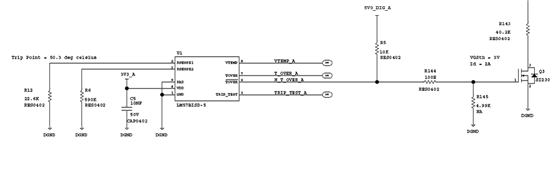
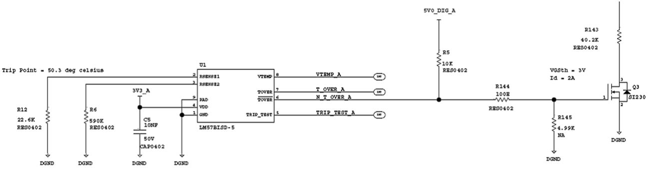
1. Do I need to connect the Thermal Pad to GND? The pad is connected to GND and I see (-6) Celsius when the device is in room temp, is it related to the Pad?

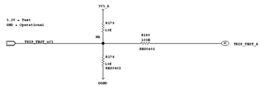
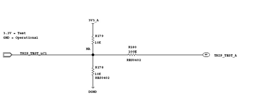
2. When checking Pin8 with DVM(in Trip Test mode) I get right measurments and when checking with Scope probe the voltage drops and the IC doesnt function right.

thanks,

Ziv

  • Hi Ziv,

    1. The LM57 Thermal Pad must be connected to ground as described in the pin description of the datasheet ( page 3 http://www.ti.com/lit/ds/symlink/lm57.pdf). So I don't think this is causing your problem. Make sure the Trip Test Input is grounded. What is the actual output voltage reading you are getting on the VTEMP output?

    2. What do you mean by "(in Trip Test mode)' is the trip test voltage high or low?
              Can you send a schematic? 
              Also make sure your scope probe is functioning correctly. It is a high impedance probe?
              Please describe what do you mean by "doesn't function right" (are you talking about the -6'C reading)?
              Do you see any oscillations on your scope?

    Take care,

    Emmy

  • Hi Emmy,

    1. VTemp in operational mode (Trip Test = '0') = 1.12V – equivalent to about -8deg Celsius. This is also problematic since it's measured in room temp.
    2. Test mode = Trip Test = '1'. The probe's input impedance is 1MOhm.  If the normal VTemp measured with DVM is 1.12V, when measured with scope = 0.68V.

     Attached are the schematics:

    Thanks,

    Ziv

  • Hi Ziv,

    Sorry but can you please snd the schematics with better resolution. I can't make out the values and most of the text.

    Thanks,

    Emmy

  • Hi Emmy,

    Sorry for that, hope now its better.


    Thanks,

    Ziv

  • Hi Ziv,

    This is much better!! Thanks!

    Emmy


  • Hi Ziv,

    Here's my reply:

    1. VTemp in operational mode (Trip Test = '0') = 1.12V – equivalent to about -8deg Celsius. This is also problematic since it's measured in room temp.

    • Are you actually probing at the pins of the device to make sure that TRIP TEST is less than 0.5V - as 0.5V is the logic low threshold voltage of the TRIP TEST pin. The logic high is 0.5 less that VDD, which in your case is 3.3V, so you need at least 2.7V on the trip test pin.

    2. Test mode = Trip Test = '1'. The probe's input impedance is 1MOhm.  If the normal VTemp measured with DVM is 1.12V, when measured with scope = 0.68V.

    • The datasheet shows the following: "In addition, when the TRIP TEST pin is pulled high the VTEMP pin will be at the VTRIP voltage."
      So based on your resistor settings the temperature threshold should be 50.3°C and the VTEMP voltage should be around 842mV and it looks like both readings are wrong.
      I noticed on your schematic that you have the TRIP TEST pin connected to R178 and R179 and they are both 10k ohms. Why are they there? Have you tried removing these to see what happens? Also, R180 of 100k may be marginal depending on how high a voltage the controller connected to uC1 can go to. The max bias current is 3uA for this pin, so you could get a 300mV drop therefore the pin not be able to go to the proper levels.

    Let me know what you find out.


    Take care,

    Emmy


  • Hi Ziv,

    Were you able to resolve the issue?

    Thanks!

    Emmy

    Precision Systems Applications

    Texas Instruments

  • Hi Emmy,

    Thank you very much, it was very helpful.

    Thanks,

    Ziv

  • You are welcome - glad to here you were able to solve your problem!

    Take care,

    Emmy