This thread has been locked.

If you have a related question, please click the "Ask a related question" button in the top right corner. The newly created question will be automatically linked to this question.

Nonlinearity of Temperature Sensor ICs

Other Parts Discussed in Thread: LM45
  1. Can someone show me graphically how to interpret the nonlinearity parameter of a temperature sensor IC?  As an example, the LM45 has a nonlinearity limit of ±0.8°C.
  2. How does the nonlinearity parameter relate to the sensor gain (average slope) range/error?  The LM45 has a sensor gain ranging from 9.7 mV/°C to 10.3 mV/°C.  

LM45 Datasheet http://www.ti.com/lit/ds/symlink/lm45.pdf

Thank you,


  • Hi Eric,

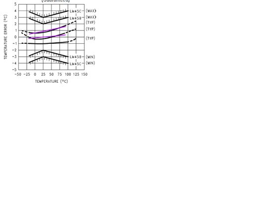
    The non-linearity is based on a best fit straight line method on the output transfer function of an LM45. Each LM45 would have a different best fit straight line or slope. That is if you were to draw a line that best approximates the slope of an LM45 let's say you determine you would get the least error from a line that has a slope of 10.3mV/C, then the non-linearity describes how far away the output would be from that slope at all temperatures. Here I overlaid two fuchsia straight lines onto two of the typical LM45 error curves. The linearity error is the difference between the black line and the fuchsia line for each LM45. Thus the min max slope does not directly relate to the non-linearity error, but both contribute to the overall error.

    Take care,