This thread has been locked.

If you have a related question, please click the "Ask a related question" button in the top right corner. The newly created question will be automatically linked to this question.

LM26LV Manufacturing Issue Pin 1 marking not visible causing risk of wrong polarity

Other Parts Discussed in Thread: LM26LV

Hi,

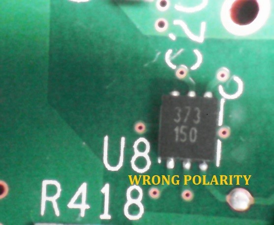
We have repeating issue in our manufacturing related to polarity of TI product LM26LVCISD-150/NOPB. Based on the physical marking, the pin 1 is not clearly indicated on the upper body. This has caused high risk of wrong polarity of the chip being mounted on board. Understood that the pin 1 can be interpreted from the bottom of the chip but this is impractical. We would like to seek TI's initiative to improve this by adding a visible dot marking to clearly indicate the location of pin 1 on the chip.

Pin 1 marking not visible on the upper body.

Difficult to locate the pin 1 location from the pad layout (bottom of the chip)


Thank you.

  • Hi Norzulaikha,

    I'm sorry to hear that. That's very strange. I checked TI's database, and it indicated that the pin 1 marking should be below the top marking "150". The Pin 1 orientation is lower left hand corner.

    +---------+
    |             |
    | YML     |
    | 150      |
    |             |
    | o          |
    +---------+

    I am absolutely agreed with you that it is very hard to identify the pin 1 marking underneath the package body during manufacturing; however, there is a way to identify the polarity during manufacturing assuming that you are using the tape and reel. On page 28 of the LM26LV datasheet, there is a description and pictorial for your information. If you look at the tape and reel, the sprocket holes should be on the top, and quadrant Q1 should be pin 1 marking.

    Hope this helps!

    Please let me know if you have further question.

    Aaron

  • Hi Aaron,

    Thanks for your prompt feedback. If you kindly refer to the attached picture, no dot marking visible for the pin 1. We have no issue setting the pin 1 orientation when loading the part with tape and reel as we will follow the spec provided in the datasheet. The issue occurs during AOI inspection and rework which technician and operator unable to identify the pin 1 location once the part is mounted or removed from board. Please help to forward this issue and help to improve future lot to have the dot marking.

    Your help is very much appreciated.

  • Hi Norzulaikha,

    I have forwarded this matter to our Customer Quality Engineer. This will be addressed by our A/T site.

    Aaron
  • Hi Aaron,


    Noted, thank you very much for your help.

    Zulaikha

  • Hi Aaron,

    Kindly help share the contact for the respective Customer Quality Engineer who is working on this issue so we can follow up. We may involve our end customer if required. Your help is very much appreciated.

    Thank you.
  • Hi Zulaikha,
    I'm sorry for the long delay. Please give more time while I am trying to contact other people to resolve this issue. Stay tune...will inform you once I get the confirmation.
    Aaron
  • Hi Zulaikha,

    The package is a small QFN 2.2 x 2.5 mm. I got an update that the team is currently looking into the current equipment and process capability whether this can be done. They will get back to me sometimes next week.

    Aaron