This thread has been locked.

If you have a related question, please click the "Ask a related question" button in the top right corner. The newly created question will be automatically linked to this question.

About LED driving board structure

Other Parts Discussed in Thread: OPT9221, TPS61165, OPT8241, LM3409, SN74LVC2T45

Hi Subhash,


I want to use an aluminum substrate PCB for dissipating the heat of LEDs.

There are only several LEDs on the aluminum substrate board.

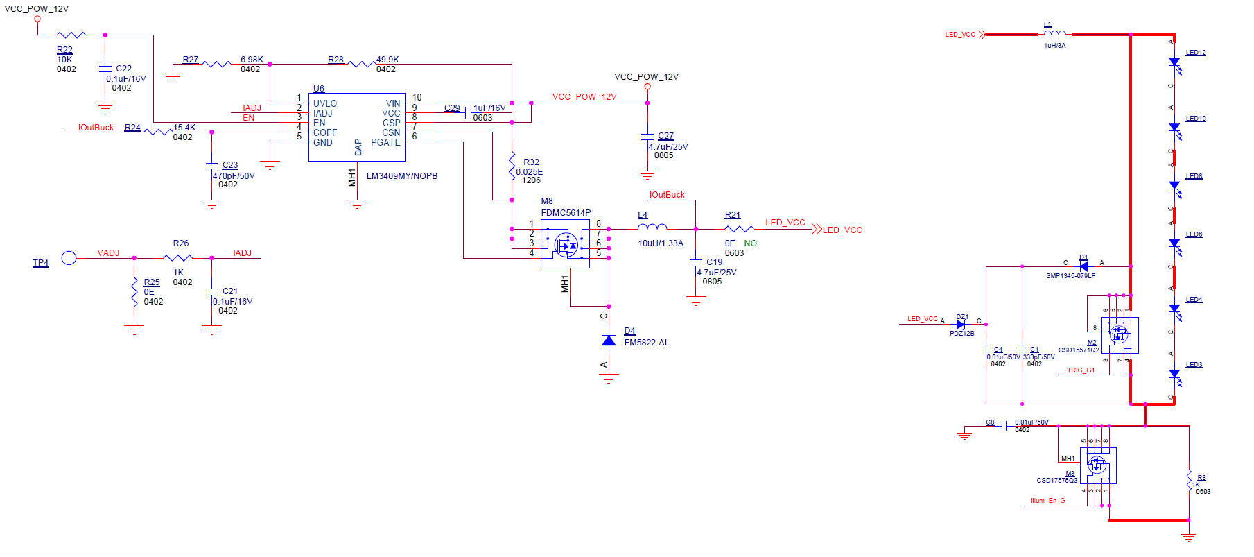
The other LED driving parts(include inductors,MOSFETs…etc) are on another board.

Then the aluminum substrate board connect to another board with a cable.

Please confirm if they can work well?

  • Hi Eric,

    The LED-MOSFET connections and the MOSFET-MOSFET Driver connections carry high currents at high frequencies. It is important to have them on the same board as circuit parasitic inductance has to be very small for the camera to function well. If you want to minimise the number of components on the LED board, I would recommend the following minimum set of components:

    1. LEDs
    2. MOSFET
    3. MOSFET Driver
    4. Snubber
    5. AC decoupling capacitors

    The above components usually have high currents flowing at high frequencies among them. It is important to achieve very low parasitic inductance in the board layout for alll these components.
    It is not necessary to have the inductor on the same board, but it would reduce emi to some extent. Can you share more details of number of LEDs, etc and the actual circuit you are using?

    Regards,
    Subhash
  • Hi Subhash,

    I plan to use 12pcs LED to achieve 8m distance.

    Could you provide me some reference circuit for driving LED?

    My application condition as below:

    Input voltage: 5V

    LED VF: 2V at 1A

    FOV: 100 degree

    Distance: 6m, up to 8m.

     Do I need to reserve “Path Delay Correction” circuit? If it needed, please let me know how to implement.

    Eric

  • Eric,

    Implementing 12 LEDs can be challenging. And LEDs typically have higher peak current rating as compared to average current rating. It is a good idea to reduce the number of LEDs and increase peak currents. Please refer to this post for calculating number of LEDs. The discussions also have the method for calculating peak current of the LEDs.

    Also, it is easier to design power supply for high power if you have high supply voltages. Do you have a higher voltage supply (~12V) on your board?

    About "Path Delay Correction" circuit, it is not necessary to implement it. It is possible to compensate for temperature dependent delays by using OPT9221. I will get back to you on the details of implementation.

    Regards,
    Subhash

  • Hi Subhash,


    I worry about reducing the number of LEDs cause the lower illumination.

    I hope to keep more LEDs for reserve.


    I have 12V supply on board. Could you please provide some reference circuit?

    Can I use the normal LED driver?(like TPS61165)


    Regards,

    Eric

  • Eric,

    I am assuming that you are using Osram's SFH4715S or some equivalent LED. These LEDs will have a forward voltage of 3V.
    I would recommend that you use 2 strings of 6 LEDs. There is a 6 LED circuit in the OPT8241 CDK schematics. You can use the circuit in the page number 8 of "OPT8241-CDK-EVM IB 10-50_REV2P0V1.pdf" and replicate it twice on your board. You would need to supply current to both the circuits. For that, you could make use of LM3409.
    Can you please send me a screenshot of your system's use case using the ToF System Estimator tool?

    Regards,
    Subhash
  • Hi Subhash,

    If I use a 6 LEDs circuit, then the voltage should be higher than 12V.

    So I think I should not use 12V as input supply power.

    I should use 5V as input supply power, and choose a boost converter, right?


    Here is the screenshot of ToF System Estimator tool:

    I can not use larger aperture lens due to cost issue, I just choose a universal lens in our industry.

    Regards,

    Eric

  • Eric,


    Running the LEDs at 50% integration duty cycle, you should be able to get optical peak power of more than 1W per LED. Please refer to the duty cycle vs peak current data on the  datasheet of the LED.

    And I also see that your range is 8m. Are you aiming for an outdoor application? If you expect the camera to work  in sunlight, you would have to account for ambient light in the system estimator tool.

    About the voltage, the final combination of inductor + switch doubles the peak output voltage like a boost converter with 50% duty cycle. You will only see about 9V or 10V at the output of the LM3409 converter. You would not be able to use TPS61165 because of the limitations in the amount of current TPS61165 can drive.

    Regards,
    Subhash

  • Eric,

    We have identified a lens which is F 1.2 and ~90 degree diagonal FoV. This might give you a better performance in the system.

    Lens part number: 1LS1097F
    Lens manufacturer: AOET
    Contact: sd@aoet.com.tw

    We would recommend that you use this lens for your application. Using this lens will give you more FoV and at the same time, improve performance as compared to the F 1.8 lens. You might be able to use fewer LEDs which will make the design simpler and maybe offset your costs.

    Regards,
    Subhash
  • Hi Subhash,
    Could you please help to check the attached schematic for driving 12 LED?
    Can I use only one mos driver(SN74LVC2T45)?
    Please let me know if something wrong.
    Thanks.
    Regards.
    Eric

    LED driving circuit.pdf

  • Hi Eric,

    You would have to use 2 MOS drivers as we have to drive the MOSFETs at a very high frequency.

    I have attached a PDF of the schematic along with the comments.

    LED driving circuit_comments.pdf

    Please let me know if there is any other part of the design you would like me to review.


    Regards,
    Subhash

  • Hi Subhash,

    Could you please help to check attached LM3409 circuit?

    It doesn't work, I don't know what's wrong.

    Thanks.

    Best regards.

    Eric

  • Hi Eric,

    I missed out on responding to this thread. Can you tell me if this is working yet? If not, can you tell me what are the conditions and symptoms?
    Few issues that I notice with this circuit:

    1. EN pin of LM3409 is pulled up to 12V. So if the sensor board is not powered, but the illumination board is powered, it will cause the ILLUM_EN pin of OPT8241 to break down due to 12V input.
    2. M3 is being controlled with ILLUM_EN. When M3 turns off, it will suddenly stop all the current. The combination of D1, D2 will work as freewheeling diodes for inductor L1. L3 would still try to force current through and may end up damaging some part of the circuit. Did you see that the circuit was not working from the start or if it worked for a few seconds and then stopped working?
    3. Can you try replacing R8 with a 0 ohm resistor? that should resolve some of the problem

    Regards,
    Subhash
  • Hi Subhash,I have resloved the issue, thanks.Regards,Eric