


Hi.
Ask questions during the design of the LM35AH NDV package.
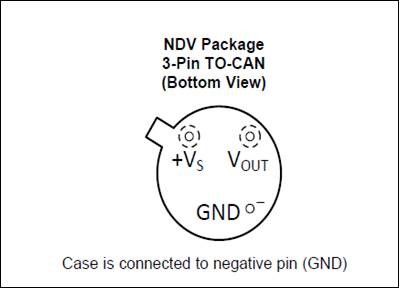
--> Is the bottom correct?
--> Is the TOP correct?
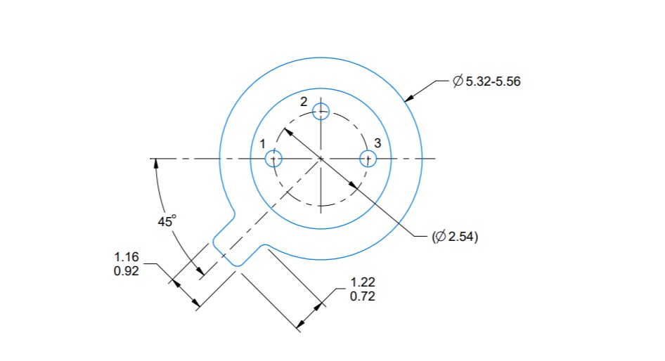
--> Is this the drawing from the bottom of the PCB?
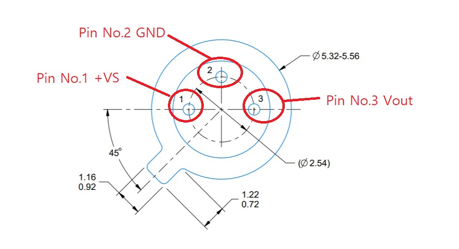
Is the pin map shown below correct?
1. +VS
2. GND
3. Vout
please answer me.

Thanks.

