This thread has been locked.

If you have a related question, please click the "Ask a related question" button in the top right corner. The newly created question will be automatically linked to this question.

AWR1642BOOST: Hardware trigger when using with TSW1400EVM and MMWAVE-DEVPACK ?

Part Number: AWR1642BOOST
Other Parts Discussed in Thread: AWR1642, , AWR1243

Dear TI support ,

I have TSW1400EVM, MMWAVE DEVPACK and AWR1642BOOST connected together. Software triggering has been working but i still have no luck getting the hardware trigger. I was trying to do it through EXT_TRG_INPUT, which is an SMA connector on TSW1400EVM probably (naively) thinking it somehow has been connected to the appropriate pin (SYNC_IN?) on AWR1642BOOST.Schematic tracing shows there is no connection or output signal from the FPGA that is driving SYNC_In on AWR1642, so i concluded from other posts (for different device, not AWR1642, that the hardware trigger should be done directly on the AWR1642 (SYNC_IN not on TSW1400EVM). Is this correct? Any details for example having to fit a 0 ohm jumper/resistor?

Or, could i do the trigger from TSW1400EVM, given that EXT_TRG_INPUT can drive SYNC1-4 on TSW1400EVM, would it make sense to get SYNC1-4 wired to drive d SYNC_IN on AWR1642? I'm not sure if this would be OK as we might have take into account the LVDS transmission time? 

If i were to hardware trigger directly on AWR1642 SYNC_IN, is there any handshake/synchronisation signal between AWR1642 and TSW1400EVM, hence the connection i was thinking above will not be necessary?

How does changing Trigger Select to Hardware trigger in Radar Studio affect Trigger Option in Data Capture Option in HIgh Speed Data Converter?-which is required to be ticked for hardware triggering as per slwu087d (or do they not talking each other?)-i believe these 2 softwares talk each other when Setup TSW1400 get executed?My observation shows that changing to hardware trigger in radar studio resulted in changes in Trigger Option changes in  HIgh Speed Data Converter? 

For TSW1400EVM the hardware requirement for trigger is also not 100% clear. The manual above specifies 1.8V, but if you look at the schematics its on the 3V bank of the FPGA.

i also have a second set of TSW1400EVM, MMWAVE DEVPACK and AWR1642BOOST and planing to connect (using SMA cables) the SYNC1(or 2,3,4) of one to EXT_TRG_INPUT of my other set as illustrated in slwu087d(master slave operation)

SUMMARY:

I need a hardware trigger for AWR1642(BOOST). At minimum, i just need it to send a frame (transmit). However because i also have TSW1400EVM i definitely want to do some data capture as well.

Any wiring requirement for doing the above?(it seems to be required from what i can see?). Please specify the correct sequence in Radar Studio (or if Lua scripting is required) and High Speed Data Converter (if required). 

If triggering through TSW1400EVM is possible (probably need wiring), then please clarify if it's 1.8V or 3.3V (question raised above). As you know with FPGA is not easy to work out as the I/O's are programmable

Last question what is the marking for silicon ES 1.0 vs ES 2.0

Thanks! I have been posting on some other posts with no luck and unable to find any answer on this forum. I also submitted SR # 1-3694176368 

I understand the the device is still in preview mode hence there are very limited reference at this stage. We have however spent around $4,000 to purchase 2 sets of TSW1400EVM, MMWAVE DEVPACK and AWR1642BOOST

Best Regards

  • Hello ,

    For the hardware trigger, what is the pulse width you are supplying for the SYNC_IN?

    -Raghu
  • Hi Raghu,
    Thanks for your reply.
    In any cases the trigger signal would be a very wide pulse width (most likely a one-off pulse only with a width of 500 ms, or even 1s! (lowest freq from my signal generator)

    No I have *not* tried on SYNC_IN . As i mentioned above i originally tried on EXT_TRIG_INPUT of TSW1400EVM (naively thinking you guys have "integrated" those 3 boards together). In any cases could you please suggest if

    #1 i should trigger from SYNC_IN (need to fit a jumper/0 ohm?) . If this is the case i assume there is already some sort of synchronisation/handshake with TSW1400EVM?(either hardwired or through Radar Studio&HSDC Pro)?-pls confirm

    #2 i should trigger from TSW1400EVM's EXT_TRIG_INPUT (assuming i will need to do some wiring to AWR1642BOOST SYNC_IN perhaps from SYNC1-4 of the EVM? Please clarify if EXT_TRIG_INPUT is 1.8V or 3 (3.3?)-question above

    As long as it works either #1 and #2 would be OK for me. In any cases the trigger signal would be a very wide pulse width (most likely a one-off pulse only with a width of 500 ms, or even 1s! (lowest freq from my signal generator)

    Regards
  • Hello Ucu,
    There is no connection from the TSW1400 EXT_TRIG_INPUT to the radar device, since thats a trigger for the FPGA and not the radar device. So you need to use option #1 indicated by you. ie feed the SYNC_IN pulse directly on the AWR1642 EVM. For this you need to mount R165 zero ohms resister and feed the pulse on the J6 connector pin #9. Note that since the IO supply of the radar device is 3.3v , the pulse amplitude should be 3.3V

    Regarding the synchronization of the TSW, I assume you are using Radar studio tool for this testing? The way the synchronization is done is using the "TSW1400 ARM " button on the radar studio , which prepares the TSW for capture. Meanwhile the pulse on the SYNC_IN continue to come and are free running. As soon as you do "trigger frame" on the radar studio the radar frame/burst will be transmitted at the next available SYNC_IN pulse. Note that the time between TSW1400 ARM and the pulse should be <10sec since the TSW waits for only 10sec to receive the data.

    Now regarding the pulse width to be provided, note that at each pulse the radar device transmits 1 frame/burst until the programmed number of frames are sent out. Hence the pulse width cannot be wider than the frame/burst active time. For example if you have 128 chirps in the frame and each chirp is 100 usec then the active frame time is 12.8 msec and hence the positive pulse width cannot be larger than the 12.8 msec. BUT the pulse rate (ie the time between two pulses) can be as slow as you desire. This should be larger than the frame periodicity programmed in the frame configuration.

    I hope this clarifies your query.

    Regards,
    Vivek
  • Hi Vivek
    Thanks for your reply. OK i will try this and get back to you soon.
    One more question: as i was already planning to have some "master slave" between my two TSW1400EVM (SYC1-4 driving EXT_TRIG_INPUT), now that i am using SYNC_IN for triggering my 1st board (using signal generator) ,i guess can i use SYNC_OUT to trigger SYNC_IN of my 2nd board?

    Thanks
  • Hello Ucu,
    Are you trying to cascade two AWR1642 here? Cascading is supported only in AWR1243 device , AWR1642 is intended for an autonomous sensors.

    Regards,
    Vivek
  • Thank Vivek. BTw may i confirm something?
    I have (separately) received confirmation that my device is of ES 1.0 siliicon
    On the other post for another device (XAR1243) (ref below) Raghunandan Kamath (TI employee) mentioned that hardware Trigger feature is supported from ES2.0 onwards. It is for XAR1243 (only) or is it also applicable to my AWR1642 ES1.0?

    e2e.ti.com/.../2301783
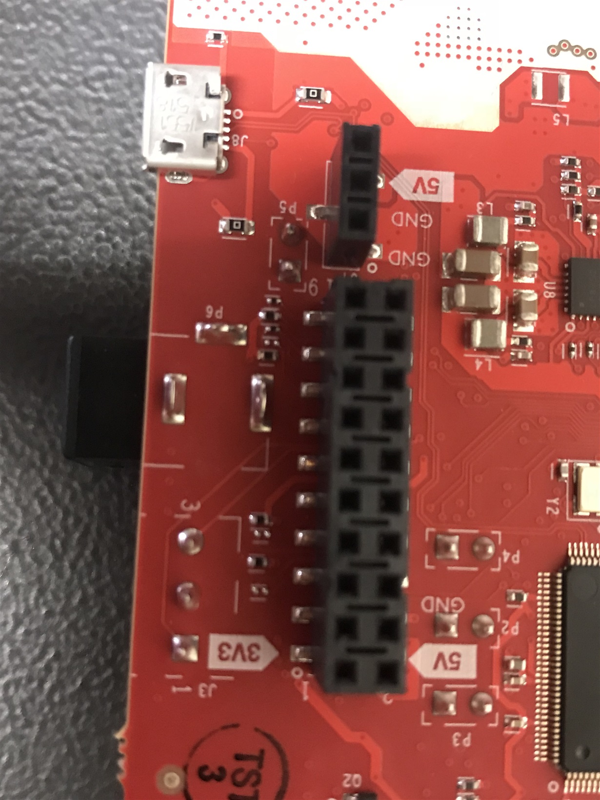
  • Oh yes, there is no place/footprint to fit R165 on my AWR1642BOOST! Sounds like is it true that i'm on ES1.0 and can't have the hardware trigger through SYNC_IN?
    Thanks
  • Hello Ucu,
    On the AWR1642 ES1.0 device the the HW triggering is supported. If you want to feed the SYNC_IN signal from the J6 connector on the EVM you would have to mount the R165 resister with 0 ohms.
    You can refer to the assembly pdf document (www.ti.com/.../sprr251) to find the exact location of the R165 resister.

    Regards,
    Vivek
  • Hi Vivek,

    Thanks for confirming about the 1.0

    yes that's exactly the document that i have been referring to, *but* as i mentioned before my *physical* dev board (hence why i attached the photo) does *not* match the document.,

    Again as i mention there is *no* footprint for mounting R165 Ohm (or jumper). *no* foot print. Please let me know should you require a higher resolution image.

    Thanks