


Other Parts Discussed in Thread: TDC7200, TS3A44159, TIDM-ULTRASONIC-FLOW-TDC
Hi team,
The customer uses TDC1000 +TDC-GP21 which is a similar TDC7200 device to design the flow meter.
He We conducts a zero flow test at room temperature and pressure. The test result is in figure 1. The figure 2 is his original design.
Compare the two test results, the beating that is the Y-axis for the original design is about ± 2ns. But for the TDC1000 +TDC-GP21
test result, the beating is about ± 4~5ns. Now the customer needs to reduce the zero flow value for the TDC1000 +TDC-GP21 design.
I found the SNIA020 document explained how to reduce the zero flow value. In the 6 Measurement Accuracy Considerations of this
document, it explains we can match the two transducers impedance to reduce the zero flow value.
For the TS3A44159 circuit, I have drawn the TX circuit and the RX circuit. Please check the figure 3.
If COM pin is connected to NC pin for TS3A44159, the TX circuit and the RX circuit are shown in the figure 3.
If COM pin is connected to NO pin for TS3A44159, the TX circuit is connected to XDC1 and the RX circuit is connected to XDC2.
So, we only change XDC1 and XDC2 through using TS3A44159 as I explained above and the capacitance and
the resistance are the same when the circuit is working. Then this can achieve the transducers impedance matching.
Q1. Is my understanding correct?
Q2. But compare to the the TX circuit and the the RX circuit, why are they different?
For the TX circuit, there is a 200 ohm resistance in parallel to the GND. Why is the 200 ohm resistance needed in parallel to the GND?
I also check the TI Design for the flow meter. TI Design :
From the schematic of this TI Design, I found the TX circuit and the RX circuit are the same that a 200 ohm resistance
and a 300pF capacitance are in series. This is different from the figure 3 circuit.
So, would you explain why the TX circuit and the RX circuit are different?
That is I would like to get the principle for the resistance and the capacitance.
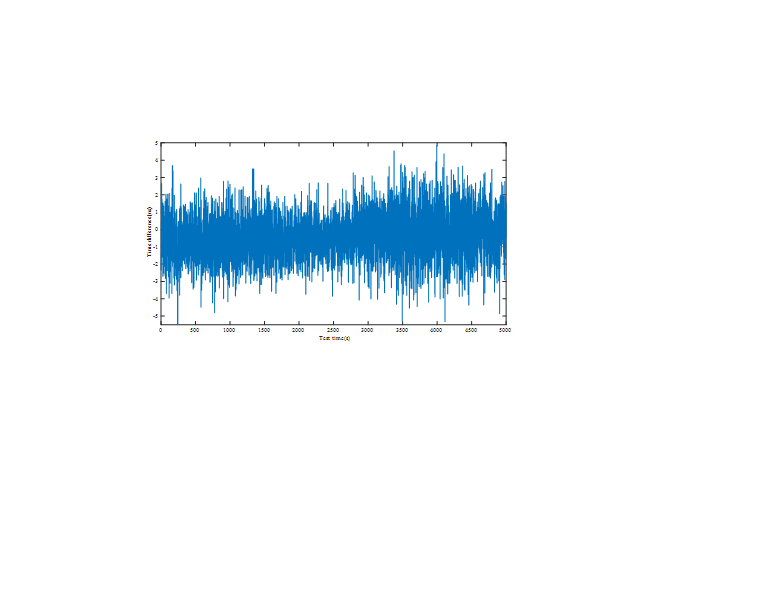
Figure 1 TDC1000 +TDC-GP21
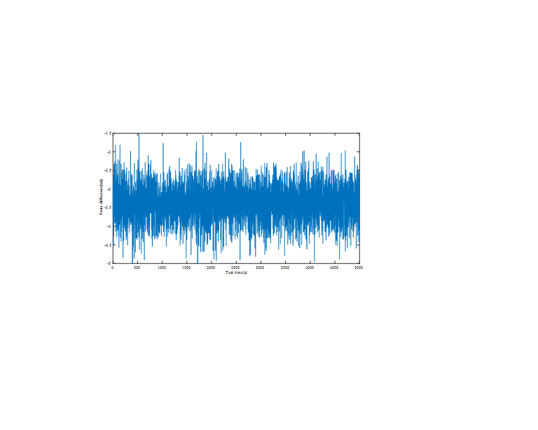
Figure 2 original design
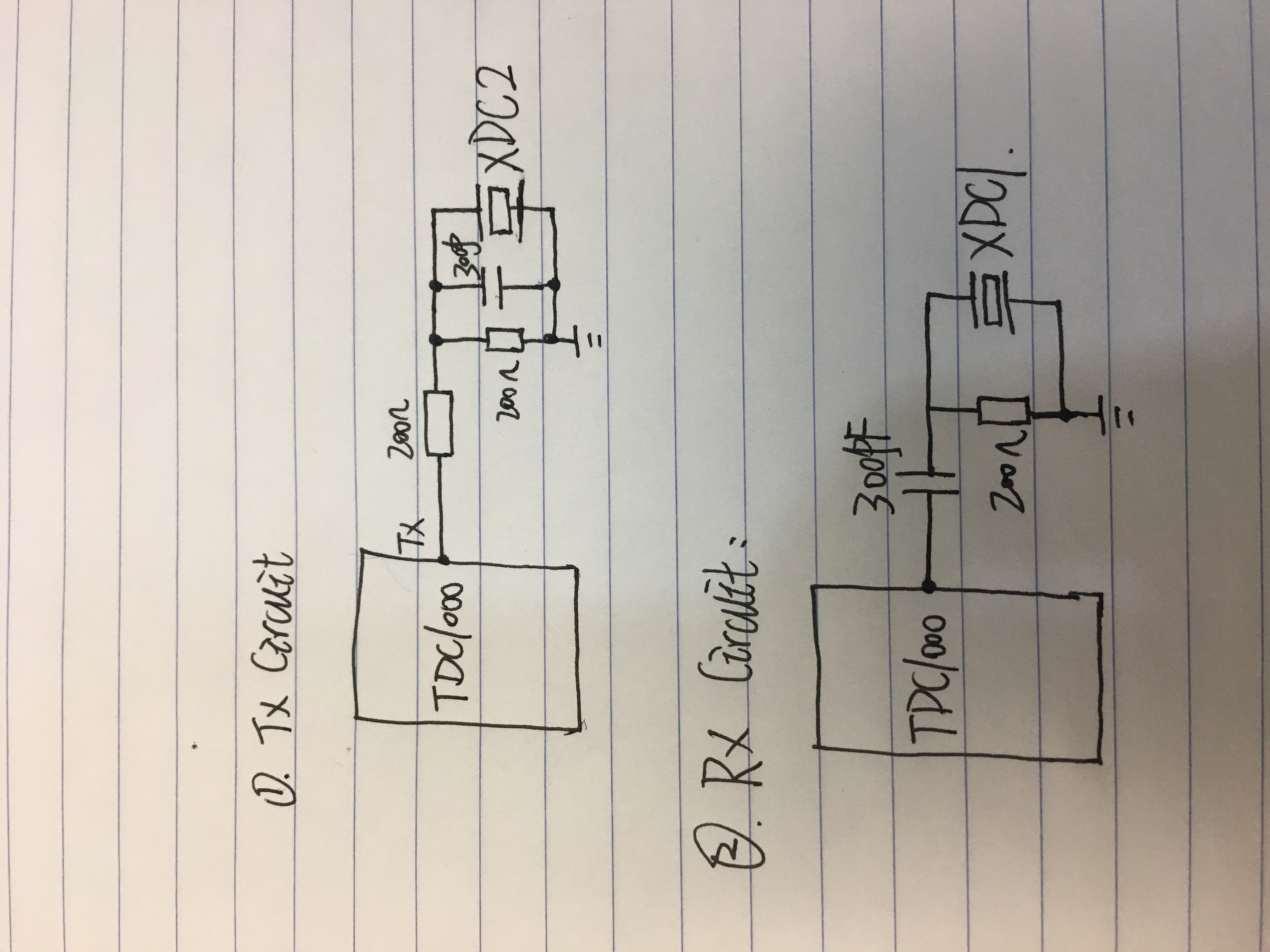
Figure 3
SNIA020:

Best Wishes,
Mickey Zhang
Asia Customer Support Center
Texas Instruments

