This thread has been locked.

If you have a related question, please click the "Ask a related question" button in the top right corner. The newly created question will be automatically linked to this question.

AWR1443: Programming new chip on custom design board

Part Number: AWR1443
Other Parts Discussed in Thread: UNIFLASH, , , AWR1243

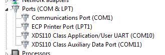
I have a custom mmWave radar PCB utilizing an XDS110 very similar to the AWR1443BOOST in a different form factor.  When I attempt to load the radar image files using UniFlash, the associated COM port locks up.  This is what the console looks like when this occurs:

Cortex_R4_0: Initialization complete.

Cortex_R4_0: Flashing process starting...

Cortex_R4_0: Connecting to COM port COM10...

Cortex_R4_0: Reset connection to device

Cortex_R4_0: Set break signal

I have verified that the SOP configuration is correct.  Any help would be much appreciated.

Regards,

Brendan

  • Hi Brendan,

    Would you be able to post a screenshot of your Uniflash with console and also Device Manager? Would you be able to post a picture of your board? I'm sorry but do not yet have enough information in order to assist you.

    Cheers,
    Akash
  • Hi Akash,

    I believe the problem is with my flash chip not running in Quad mode.  The flash chip on the AWR1443BOOST is no longer recommended for new designs so I am using the following component:

    S25FL064LABNFV040.  It does not default to Quad mode and I need to write to it via UART on the AWR1443.  My design has an XDS110 emulator on board just like the AWR1443BOOST.  I was hoping to utilize the RS232 connection from the XDS to the AWR1443 chip in order to program the flash into Quad mode.

    Any thoughts?  I will work on getting pictures of the board but may take some time to get approval from my customer.  Thanks in advance.

    Regards,

    Brendan


  • Hi Brendan,

    I'd recommend a couple of things, first confirming that your COM10 port is for Class Application UART and not Auxiliary data as shown in the Device Manager.

    I'd also ask you to truly confirm you have SOP0 and SOP2 jumpers populated upon device power up to ensure the device is in flashing mode. I just recreated this error on my board by having only the SOP0 jumper populated.

    Let me know if this isn't the issue and we can look into this further.


    Cheers,
    Akash
  • Hi Akash,

    Thanks for the quick response.  Unfortunately these were not my issues.  COM10 is the UART port:

    The SOP jumpers are in the correct position.  I traced the voltage from the header pins to the AWR1443 pins to confirm that my design was not the issue.  SOP seems to checkout.

    Can I use the USB interface (COM10) to write to my serial flash via the AWR1443 chip?  I believe I need to put the flash in Quad mode.

    Regards,

    Brendan

  • Hi Akash,

    I came across this paragraph in the AWR1243 bottloader flow document:

    Is there a similar list for the AWR1443.  The AWR1443BOOST uses the S25FL116K.  Thanks much.

    Regards,

    Brendan

  • Hello,
    The valid QSPI flash devices are listed in the AWR1443 Errata Document.
    Regards,
    Joe Quintal 
     
  • Hi Joe,

    Thanks for the response.  The Errata document lists the S25FL132K0XNFB010 as one of the devices.  This device is close to obsolescence so I investigated the replacement from Cypress.  You will see in the following image the drop-in replacement for the S25FL132K0XNF family is the S25FL064LABNF family.

    Do the AWR1443BOOST eval boards need to set the flash into Quad mode at the factory before shipping out?

    Thanks,

    Brendan

  • The 64 flash does not work with current mmwave devices.  you can search for this onE2e.
    It wii work for 1443 es3 or 1642 es2.
    I suggest trying your test with a listed device in Erratta for now.
    Regards
    Joe

    Sent from my iPhone