This thread has been locked.
If you have a related question, please click the "Ask a related question" button in the top right corner. The newly created question will be automatically linked to this question.
Hi,
I'm going to use AWR1642EVM with DCA1000 to get the MIMO raw data, and generate a virtual antenna array. (as figure 5)
(FIGURE BELOW IS FROM TI DOCUMENT.)
I know that there are two TX and four RX on AWR1642EVM.
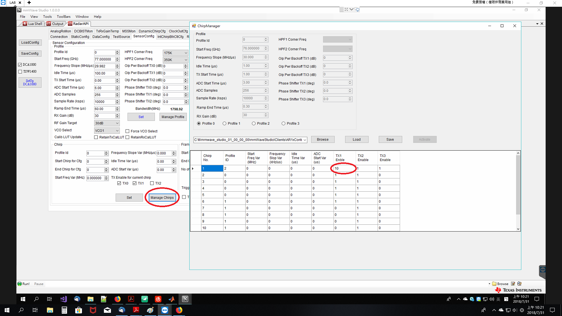
If I open only one TX, I'll get an array below:
If I open both TX, I expect to get an (8, 256*128) array. But I still get an (4, 256*128).
I'd like to know what's going on.
Is there any user guide mention about MIMO setting?
Thanks
Hi,
Here is an example of a chirp configuration that may help you understand visually
Thank you
Hi,
You need to define 2 Chirps using same profile. For chirp0, you need to enable TX0, For chirp1, you need to enable TX1.
Then you need to define frame configuration with ChirpStartIdx = 0, ChirpEndIdx = 1, numLoops = 64. See below config file in MMWAVE SDK.
Also refer to SDK example documentation for more details on MIMO
mmwave_sdk_02_00_00_04/packages/ti/demo/xwr16xx/mmw/docs/doxygen/html/index.html
Regards,
Kaushal
Hi, Thanks for your reply.
I'm still studying for these MIMO settings, and the figure you posted seems like a script file for demo visualizer.
So the setting steps may be:
1. Set Manage Profile : edit two profiles for two TX respectively. (ex: profile 0, profile 1)
2. Set Manage Chirps : mmWave studio -> SensorConfig -> Chirp ->Manage Chirps. I'm confused about setting chirps. If I have 128 chirps in a frame, it means I need to edit for each chirp ?
And I have no idea what is TX3 in your pdf file. We have only two tx antenna, right?
--
Figure below is the default setting of Manage Chirps. I also have no idea why TX enable of chirp No.1 is 10.
Thanks
Weimin
Hi Weimin,
Below are the steps for configuring TX TDM MIMO configuration. As you see I define 1 profile (Profile Id = 0). Then I define 2 chirps, 0 and 1. Chirp 0 enables TX0, Chirp 1 enables TX1.
Then in frame configuration, I enable Chirp 0 and Chirp1 and Loop them 32 times to create a frame of 64 chirps.
Regarding other comments,
TX3 is available in AWR1243 and AWR1443 which are different parts of the mmWave product family. AWR1642 has 2 TX.
Chip Manager, TX enable should be either 0 or 1. I will check if default configuration needs an update.
Regards,
Kaushal
Hi Kaushal Kukkar,
Thanks! It’s clear.
As far as I know, after I saved the raw data.
The "Odd chirps" and "Even chirps" which are the signals received from TX1 and TX2 respectively should have a phase difference "2 lambda" (TX antenna space).
When I want to check if I config the setting correctly, I calculate the phase difference between the first and the second chirps by Matlab.
But I didn't get a value equals to 2 lambda or close to 2 lambda.